Modelling, Assembling and Rendering of American Chopper
Modelling, Assembling and Rendering of American Chopper
OBJECTIVE
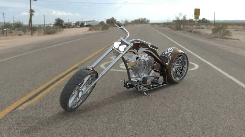
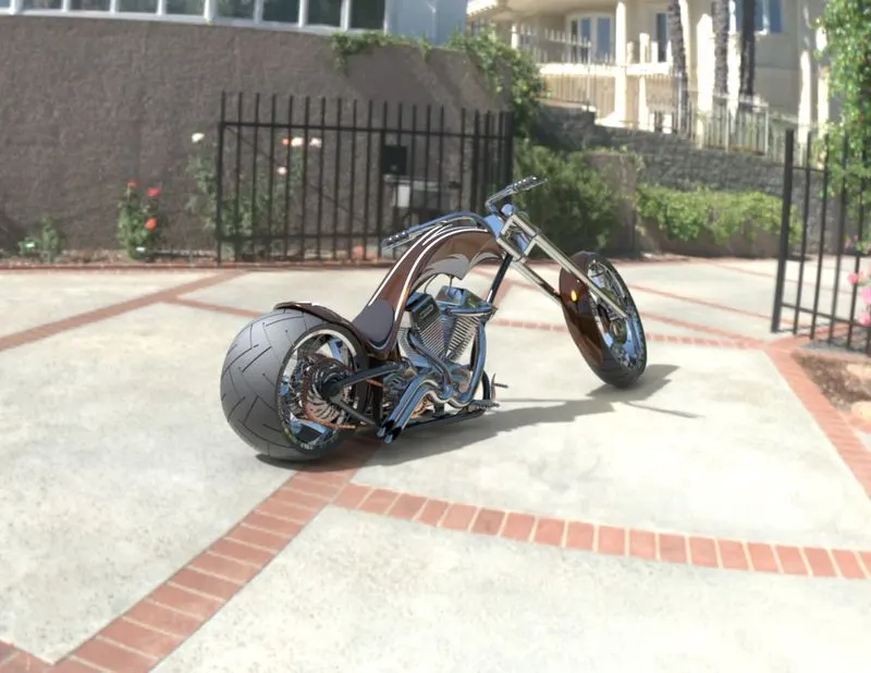
To Model the all the parts of Chopper and assembling them to create an American Chopper and render the assembled chopper to get a realistic appearance.
INTRODUCTION
By using solidwords 3D modelling software, the American Chopper is going to be modelled, assembled and rendered. In this project various types of features and options in solidworks going to be used.
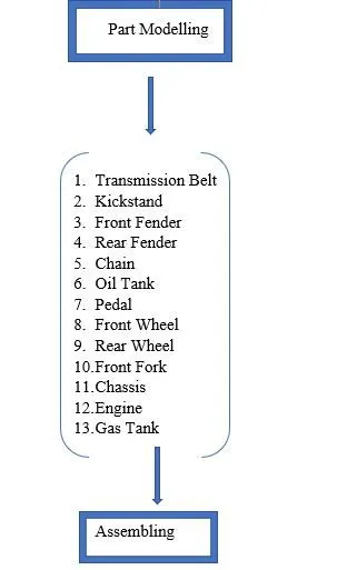
DESIGN METHODOLOGY
DESCRIPTON
Feature Definition
- Boss Extrude – tool used to extrude the 2D sketch into 3D Model
- Fillet – to avoid the sharp edges
- Loft – Used to Combine two different sketches to make it 3D Model
- Dome – applied to face to convert it into spherical or Elliptical Shape
- Cut Extrude – to remove the material from the extruded part
- Revolve – to convert the sketch to body by revolving the sketch about axis
- Split – to remove or separate one model into two like 1 sphere to 2 semi sphere or 1 semi sphere
- Shell – to remove the inner material from solid body to make it as shell
- Circular Pattern – to copy the feature/body and pasting it number of times in circular manner with a radius Value about a point.
- Combine – to combine the two or more solid bodies into single solid body.
- Chamfer – to convert the one sharp edge into two sharp edges with distance-distance or distance -angle dimensions
- Linear Pattern – to copy the feature/solid body and pasting in linear directions with number of instances.
- Trim – is the tool used to remove the unwanted sketch when two entities are merged.
- Offset – is the tool used to offset any sketch entities at required distance.
- Cut Revolve- to remove the material from the solid body by revolving the sketch about the axis
- Move/Copy – Moves or Copies the Solidbody about plane.
- Sweep – it sweeps a closed profile along the open or closed path to create a solid body.
- Projected Curves – It is an 3D curve which is created by combining the two 2D curves.
- Composite Curves – It is used to combine the two curves.
- Surface Sweep – it sweeps a Surface along the open or closed path.
- Surface Trim – It trims where a surface intersects another surface, sketch or plane.
- Surface Loft – it creates a lofted surface between two or more sketches.
- Boundary Surface – It creates a surface between two sketches that can be tangent, curvature in all directions.
- Surface knit – It combines two or more adjacent, non-intersecting surface into single surface.
- Surface extrude – It extrudes a sketch in one or two directions to create a surface.
Part Modelling
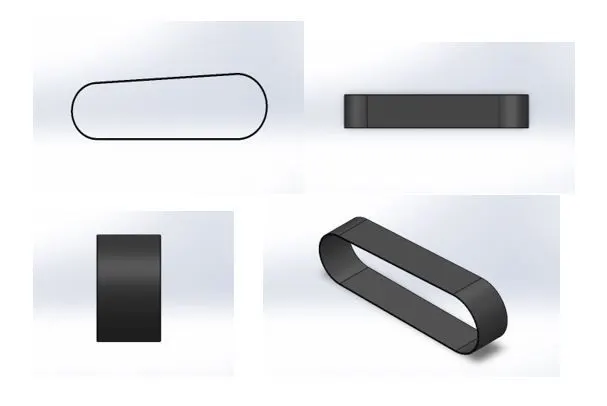
1.Transmission Belt
Transmission Belt is used to transmit the power from one rotary element to another rotary element.
Features Used:
- Boss Extrude
- Fillet
- Kickstand
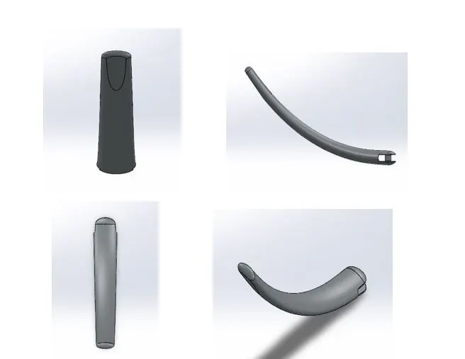
Kickstand in vehicles is used to hold the vehicle when the rider is not with the vehicle.
Features Used:
- Loft
- Dome
- Cut Extrude
- Boss Extrude
- Fillet
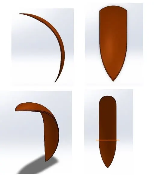
3.Front Fender
Front Fender is Front Wheel Mud Guard which avoids the mud sprinkles from tyre to Other parts and driver.
Features Used:
- Revolve
- Split
- Fillet
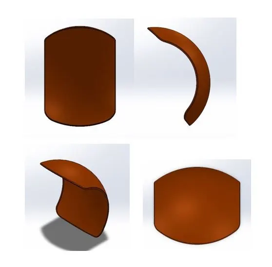
- Rear Fender
Rear Fender is Rear Wheel Mud Guard which avoids the mud sprinkles from tyre to Other parts and driver.
Features Used:
- Revolve
- Split
- Fillet
- Shell
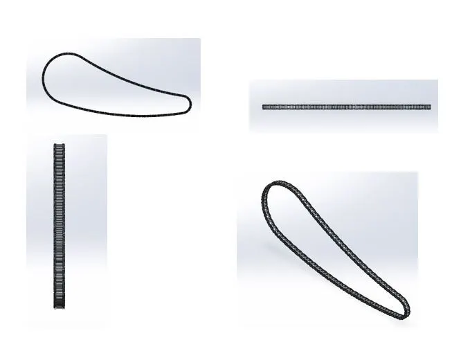
- Chain
Chain is a type of power transmission element used to transmit the power from engine to the rear wheel
Features Used:
- Boss Extrude
- Fillet
- Circular Pattern
- Mirror
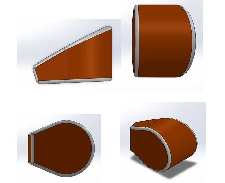
- Oil Tank
Oil Tank is a Storing Part used to store the oil required for the engine lubrication.
Features Used:
- Boss Extrude
- Fillet
- Combine
- Shell
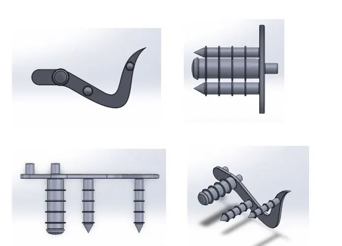
- Pedal
Pedal includes foot rest, Cluth and Brakes.
Features Used:
- Boss Extrude
- Fillet
- Revolve
- Dome
- Chamfer
- Linear Pattern
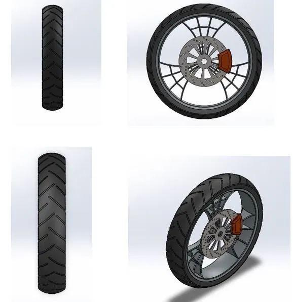
- Front Wheel
Front Wheel consists of Front tyre, Rim, Caliper, Rotor.
Features Used:
- Revolve
- Boss Extrude
- Cut Extrude
- Cut Revolve
- Circular Pattern
- Combine
- Fillet
- Chamfer
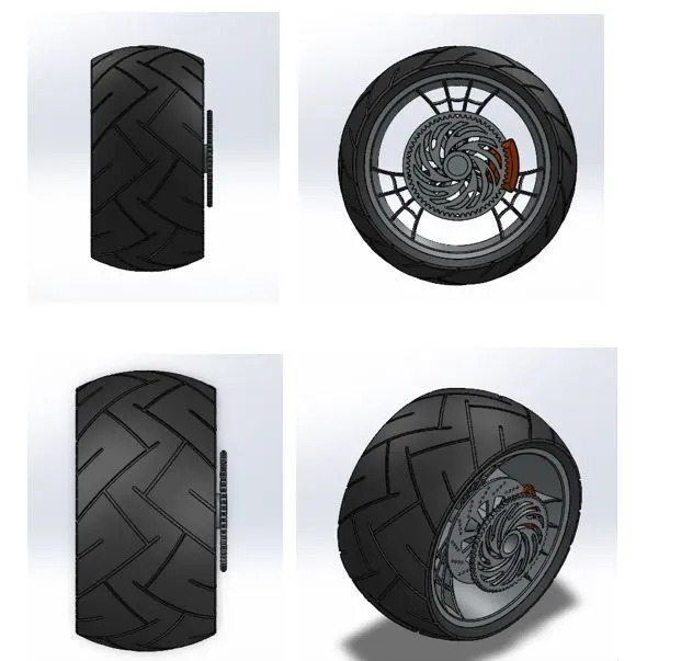
- Rear Wheel
Rear Wheel is the drive wheel of chopper. Rear Wheel consists of Front tyre, Rim, Caliper, Rotor.
Features Used:
- Revolve
- Boss Extrude
- Cut Extrude
- Circular Pattern
- Combine
- Cut Revolve
- Fillet
- Chamfer
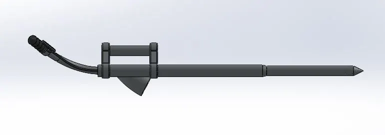
- Front Fork
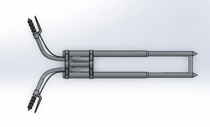
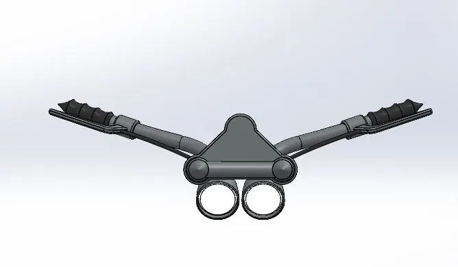
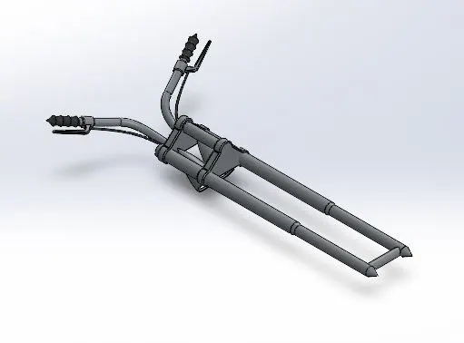
Front fork consists of Front wheel, Head Lights, Steering Handbar. It is used to steer the vehicle left and right.
Features Used:
- Revolve
- Boss Extrude
- Fillet
- Linear Pattern
- Cut Extrude
- Dome
- Cut Revolve
- Body - Move/Copy
- Projected Curve
- Sweep
- Mirror
- Combine
- Chassis
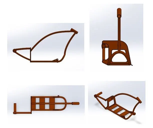
Chassis is the bone of Vehicle where all the parts are rested. Front fork,
Rear wheel, Gas tank, Engine, Pedal are to be mounted on the chassis.
Features Used:
- Projected Curve
- Sweep
- Mirror
- Boss Extrude
- Cut Extrude
- Chamfer
- Fillet
- Dome
- Split
- Combine
- Revolve
- Engine
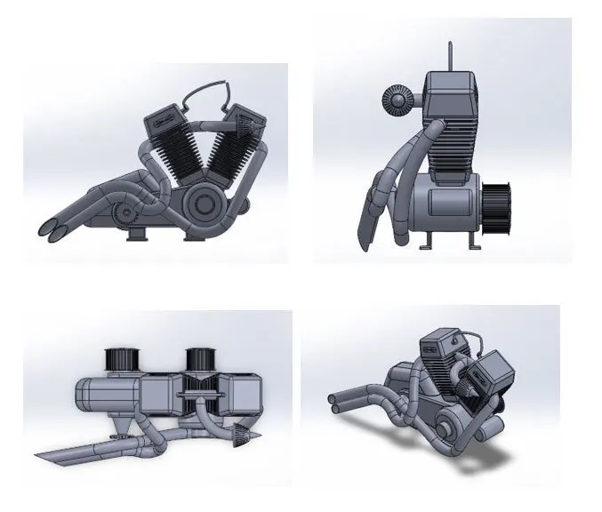
Engine is the heart of the vehicle. It generates the power and transmits to the wheels. It is an Internal Combustion Engine.
Features Used:
- Boss Extrude
- Fillet
- Revolve
- Circular pattern
- Dome
- Cut Extrude
- Chamfer
- Linear Pattern
- Mirror
- Split
- Combine
- Sweep
- Projected Curves
- Composite Curves
- Gas Tank
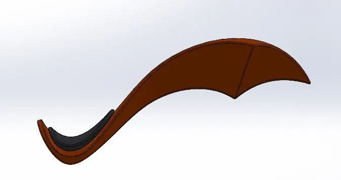
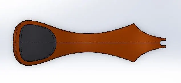
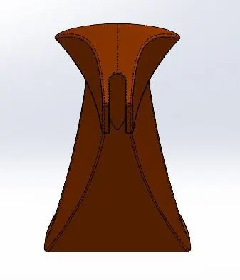
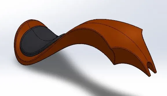
Gas Tank is the storage element used to store the fuel required for engine.
Features Used:
- Surface Sweep
- Surface Trim
- Surface Loft
- Projected Curve
- Boundary Surface
- Surface Extrude
- Mirror
- Surface knit
- Split
- Fillet
- Cut Sweep
- Shell
Assembling
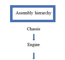
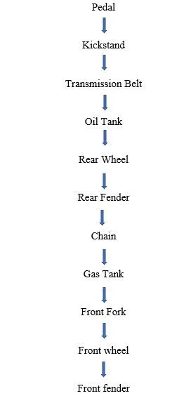
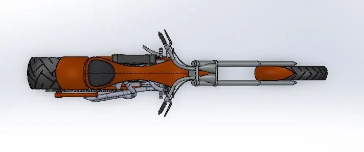
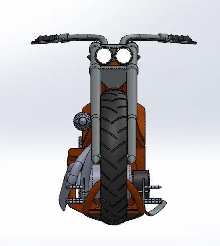
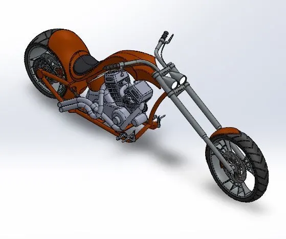
In assembling section, the modelled parts are inserted one by one and mate together to form a fully constructed chopper.
Here the chassis is inserted at first and it is fixed in space. Next other parts inserted as planes merging with chassis.
Features Used:
- Mate – Creates the geometric relationships between the components, to define the allowable directions of linear and rotational motion of the components.
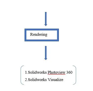
Rendering
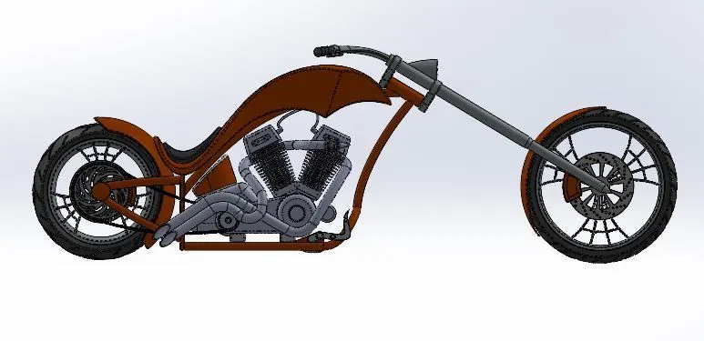
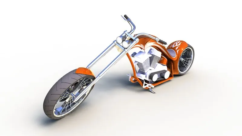
Rendering is the process of creating realistic images of an particular assembly by controlling the environment, scenes, background, brightness, lights, camera., etc.
To render the American Chopper two methods are used,
- Solidworks Photoview 360
- Solidworks Visualize
Features Controlled:
- Appearances – Colour, Material
- Scenes – Environment, Background, Brightness, Angle, Caustics
- Camera – Camera View, Perspective, Focal Length, Depth of field
Rendered Images
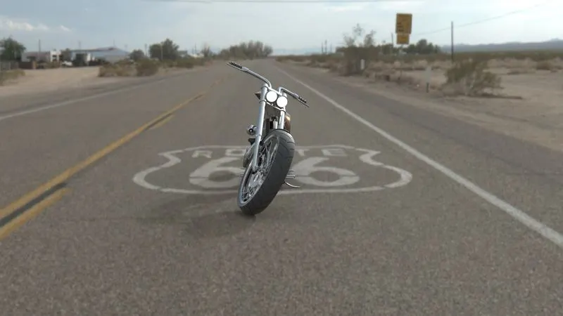
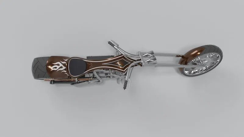
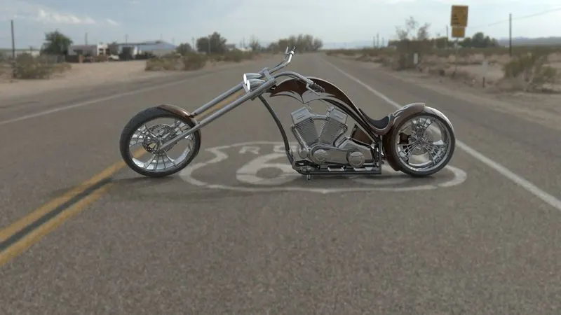
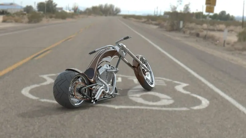
Conclusion
Thus the project on Modelling, assembling and Rendering of an American Chopper is done and the files are attached.