Advanced Sheet Metal Design Using NX Cad Challenge_6_Bracket
DESIGNING A SHEET METAL BRACKET
OBJECTIVE
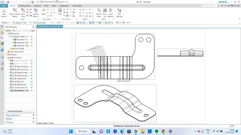
The objective of the project is to design a sheet metal Bracket using sheet metal application in Siemens NX software along with a detailed drawing sheet.
DESIGN METHODOLOGY

FEATURES USED FOR MODELLING
- TAB – Creates a base feature by extruding a sketch along a vector by a thickness value or adds material to a planar face. Additional planar sections can be added to generate bends as part of the base feature.
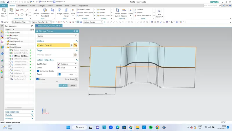
- NORMAL CUT OUT – Cuts material by projecting a sketch onto the model and then cutting perpendicular to the faces intersected by the projection.
- BEND – Modifies the model by bending material on one side of one side of a sketch line, adding a bend between the two sides.
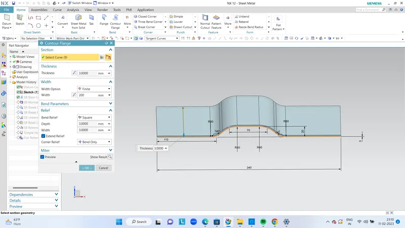
- CONTOUR FLANGE – Creates a base feature by extruding a sketch along a vector or adds material by sweeping a sketch along an edge or chain of edges.
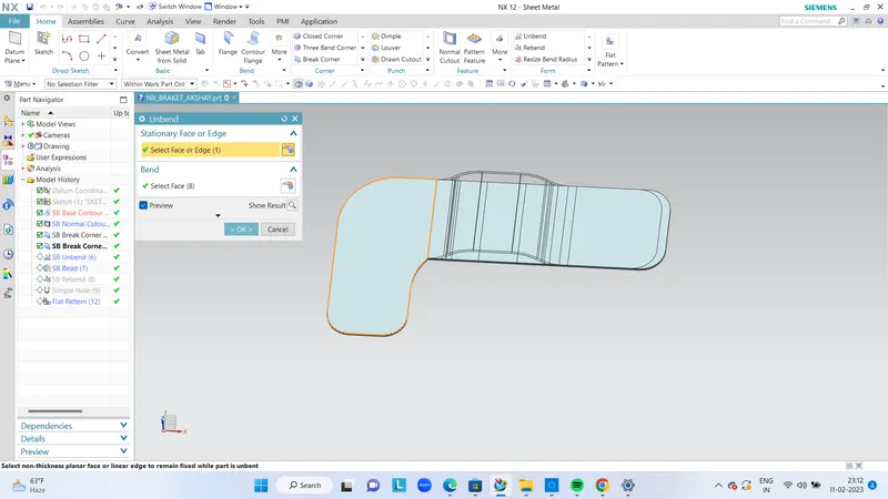
- BREAK CORNER – Rounds or Chamfer a sharp corner of a Tab or Flange.
- UNBEND – Flattens a bend and the material adjacent to the bend.
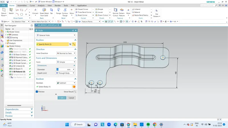
- HOLE – Adds a hole to one or more solid bodies in a part or assembly with options for counter bored, countersunk and threaded.
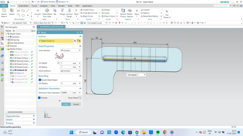
- BEAD – Lifts a material along the contour of a sketch that simulates a stamping tool.
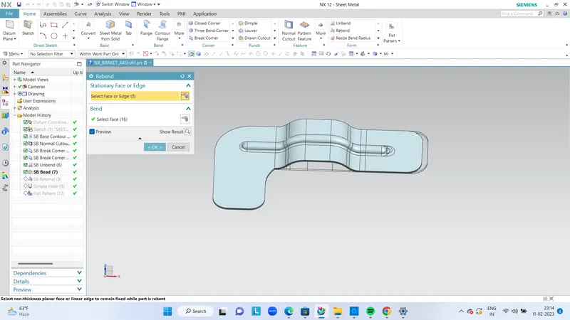
- REBEND – Restores an unbend feature to its previous bent state, along with any features added after the unbend feature.
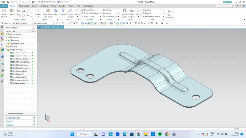
- FLAT PATTERN – Creates a flat pattern from the formed sheet metal part.
COUTOUR FLANGE
NORMAL CUTOUT
BRAK CORNER

UNBEND
BEAD
REBEND
HOLE
ISOMETRIC VIEW
FRONT VIEW
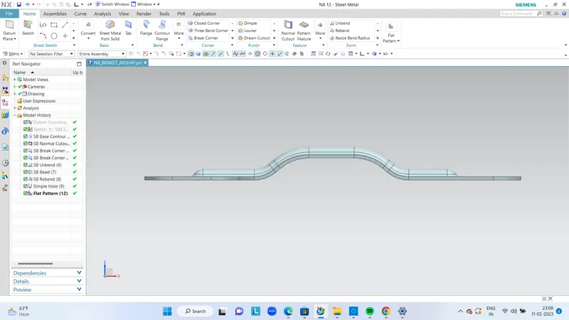
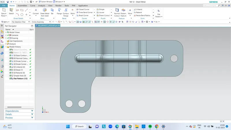
TOP VIEW
DRAFTING