Advanced Sheet Metal Design Using NX Cad Challenge_2_Box Assembly
Title of the Project: Advanced Sheet Metal Design Using NX Cad Challenge_2_Box Assembly
Objective: To design the sheet metal casing using NX CAD.
Introduction:
Sheet metal is metal formed by an industrial process into thin, flat pieces. Sheet metal is one of the fundamental forms used in metalworking, and it can be cut and bent into a variety of shapes. Countless everyday objects are fabricated from sheet metal.
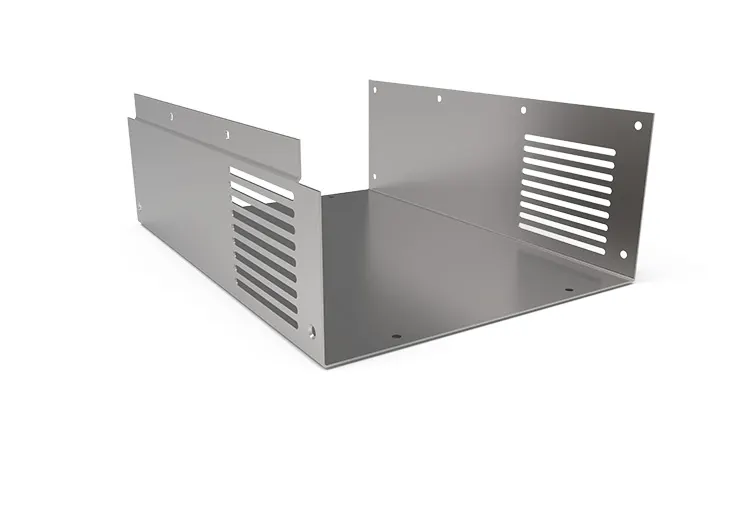
Below are the factors a designer needs to consider while modeling a sheet metal component.
- Wall Thickness
- Bend Radii
- Orientation of Holes & Slots
- K Factor
- Bend Allowance
- Bend Deduction
- Bend Reliefs
- Some Additional Features
Methodology:
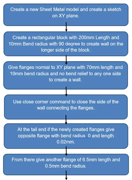
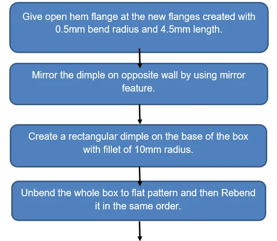
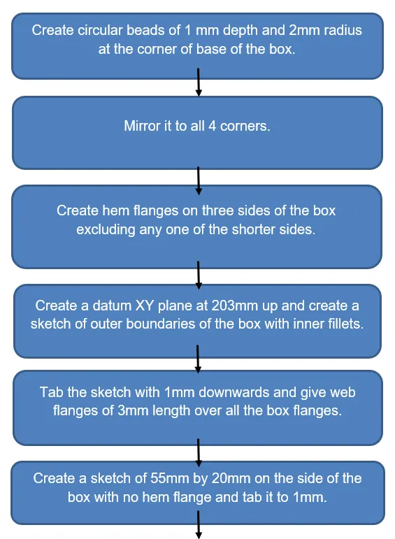
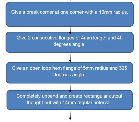
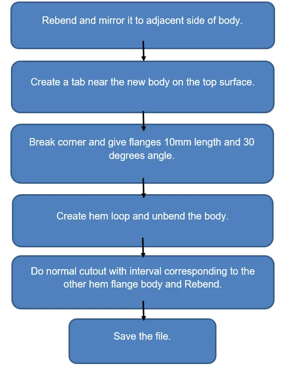
Description:
All the tools and features used are given below,
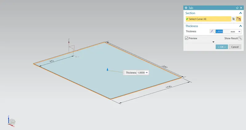
TAB: Creates a base feature by extruding a sketch along a vector by a thickness value.
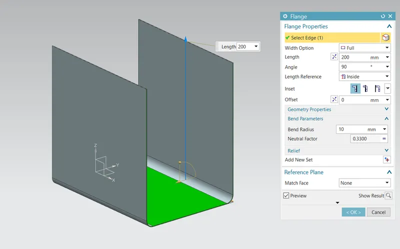
FLANGE: Adds a flange to an angle to a planar face and adds a bend between the two.
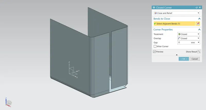
CLOSED CORNER: Closes a corner where two adjacent flanges meet by extending the bends & flanges.
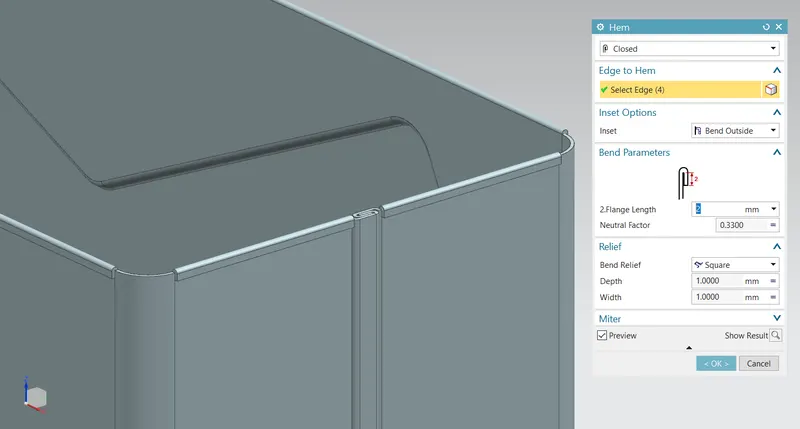
HEM FLANGE: Modifies the model by folding the edge of a sheet metal flange over onto itself for the purpose of safe handling or to increase edge stiffness.
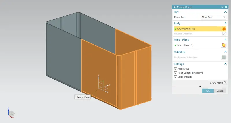
MIRROR BODY: Mirror the exact body with features to the particular plane.
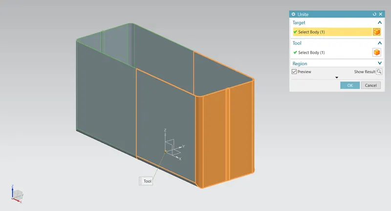
UNITE: Combine or Join the two bodies in single.
DIMPLE: Lifts an area of the model inside a sketch that simulates stamping a tool.
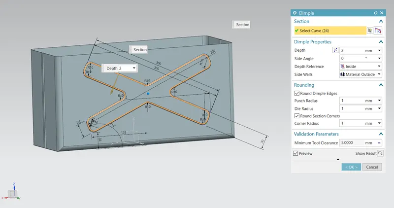
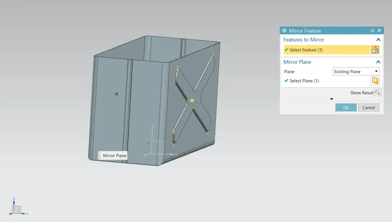
MIRROR FEATURE: Mirrors the features on the body along a plane.
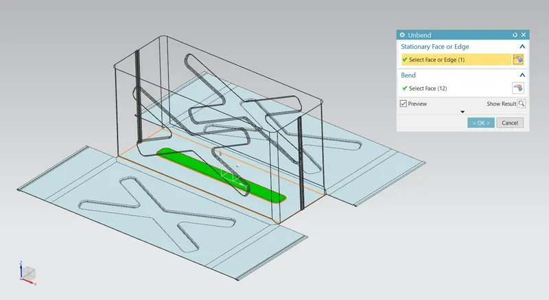
UNBEND: Flattens a bend
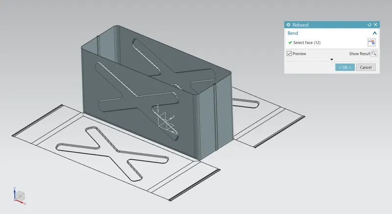
REBEND: Restores a bend
BEAD: Lifts a material along a counter of the sketch that simulates stamping a tool.
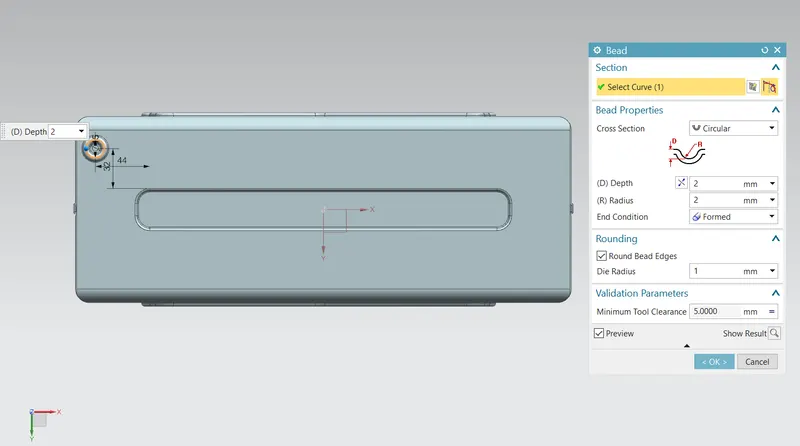
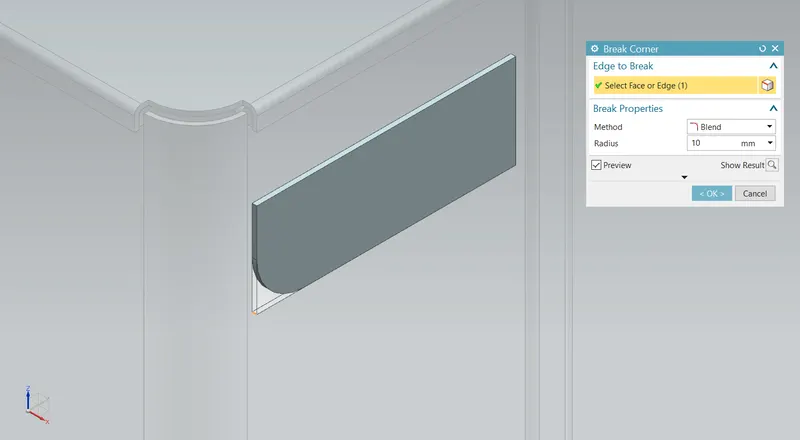
BREAK CORNER: Rounds a sharp corner.
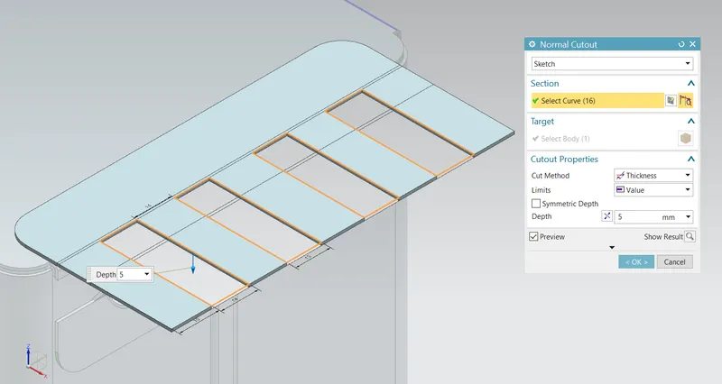
NORMAL CUTOUT: Cuts the model perpendicular to the sketch.
Final model:
Front View:
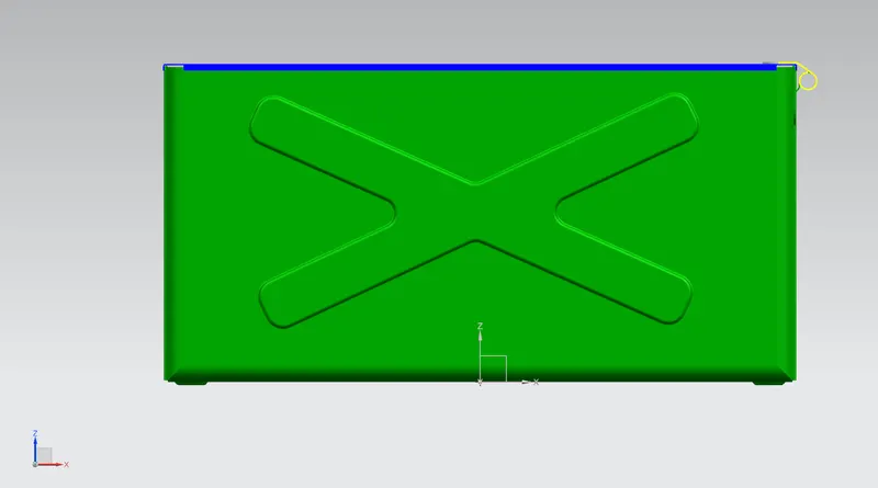
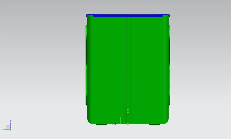
Left Side View:
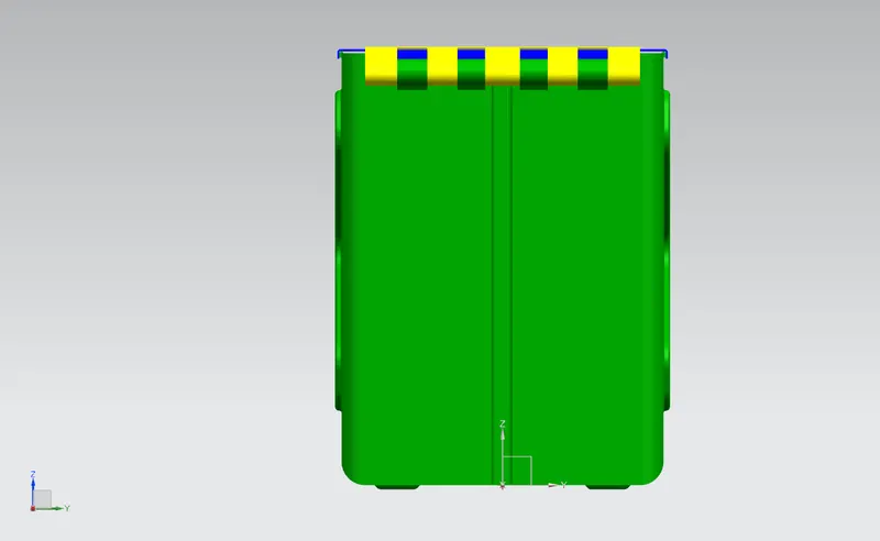
Right Side View:
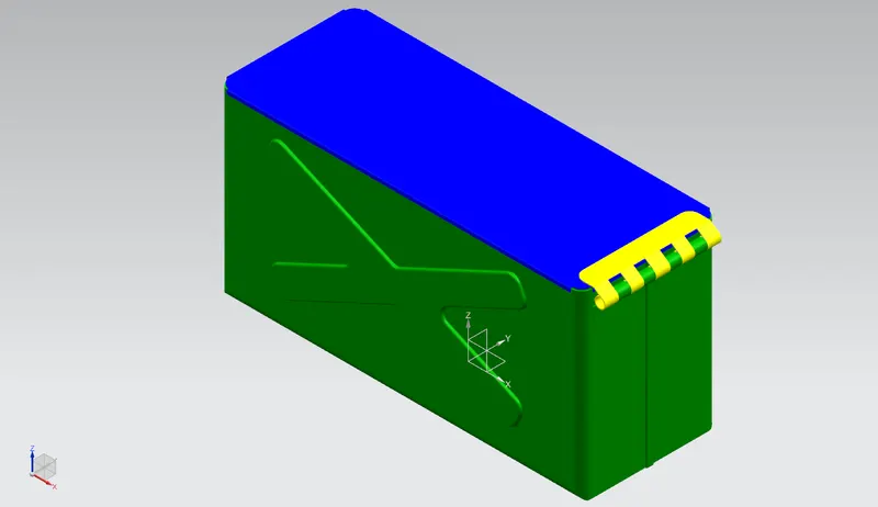
Isometric View:
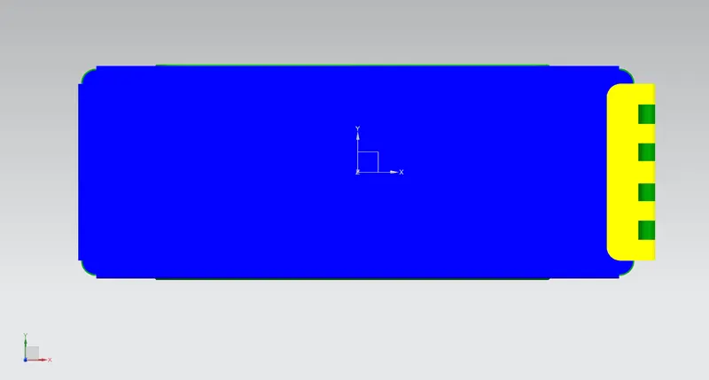
Top View:
Conclusion:
The Box Assembly Design is Successfully created considering design parameters and required dimensions.