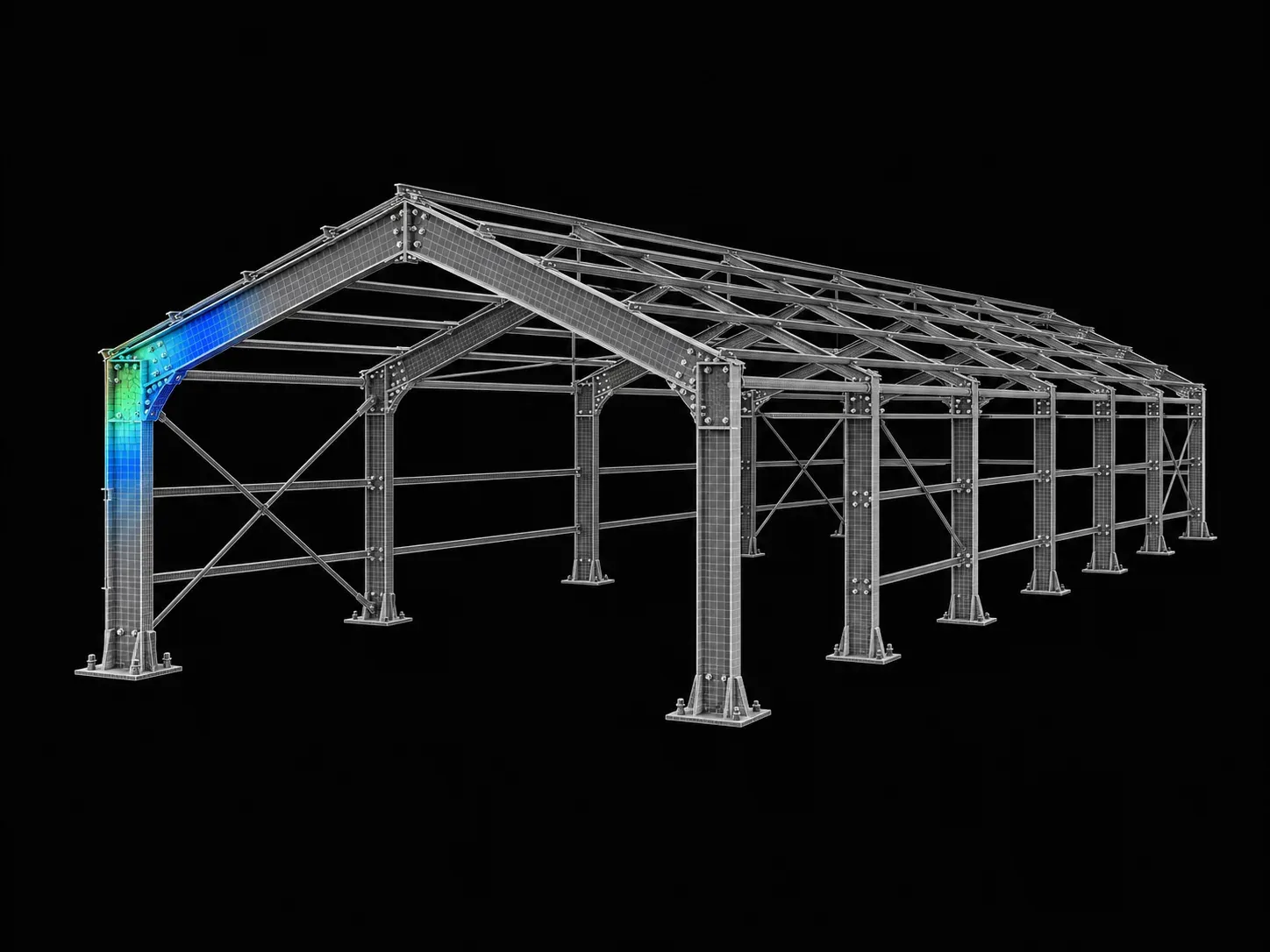
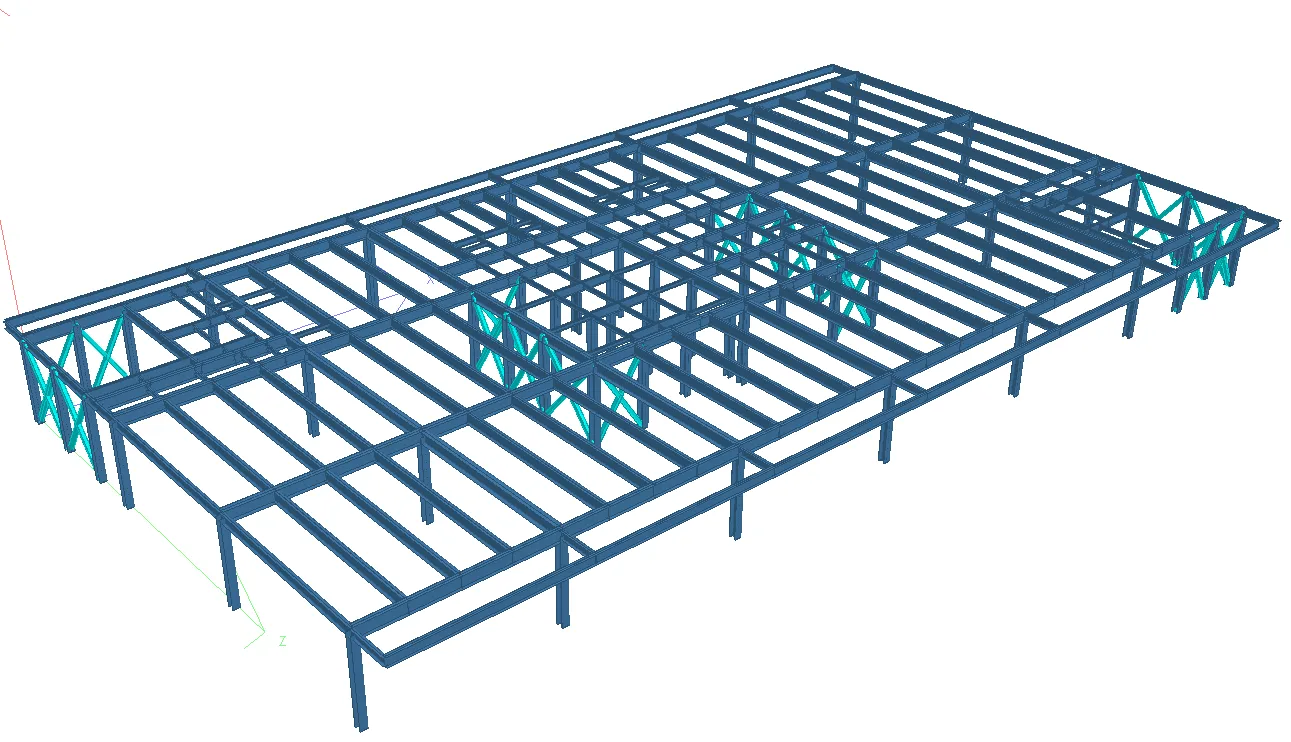
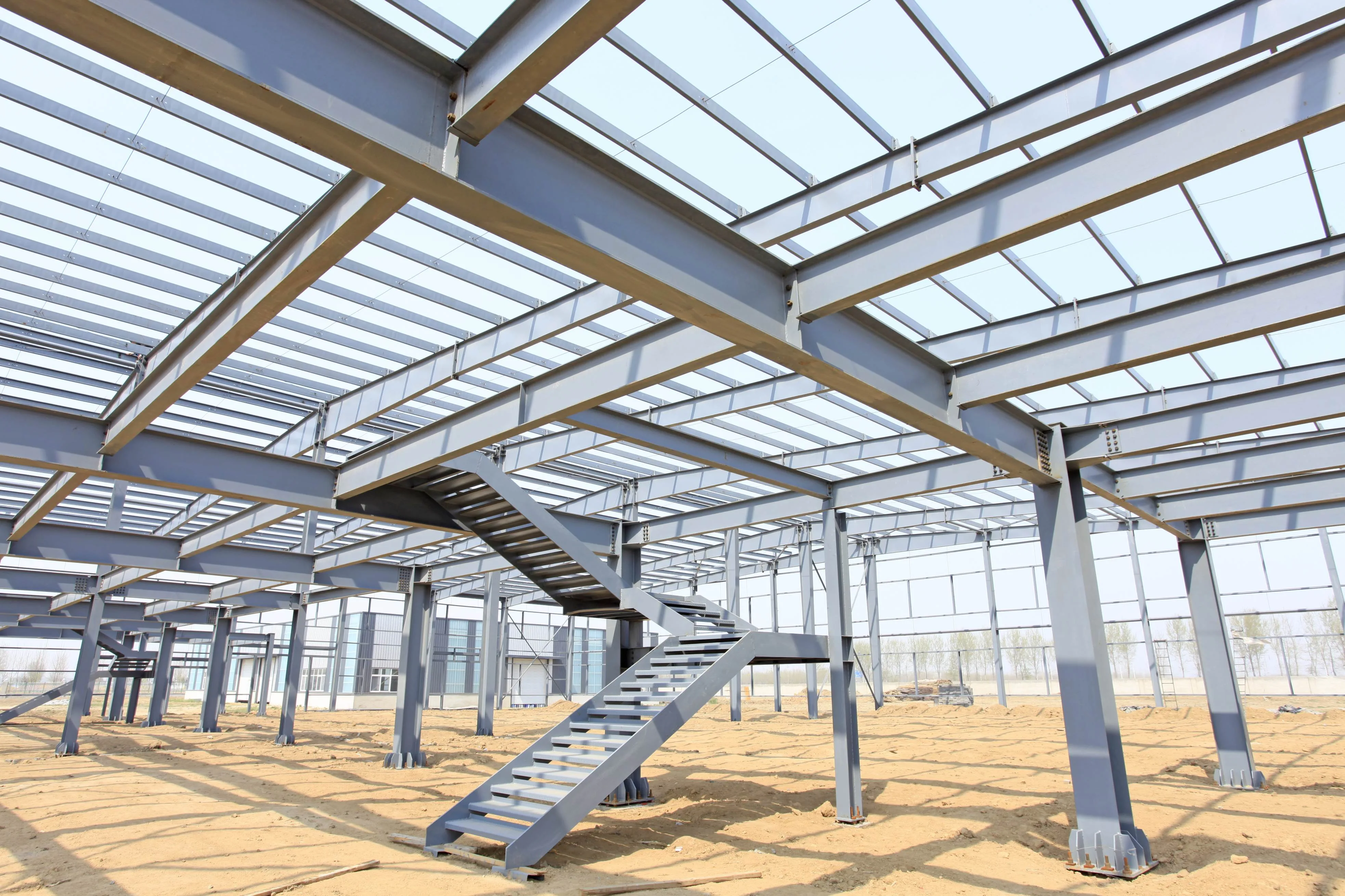
Gain a solid understanding of how to build durable and appealing commercial structures with the steel structure course. Curated by industry experts Skill-Lync's steel structure design course teaches the designing and analysing of industrial and RCC structures using industry-standard tools.
The Post Graduate Program in Steel Structures is an online PG program from Skill-Lync: 48 weeks, 152 hours of content, 8 courses and 15 industry projects.
In this course, an extensive understanding of industrial members, like compression and tension members, beams, girders are discussed.
Designing tools in STAAD.Pro, an important industrial designing software, is covered in this course.
The importance and methods of GA drawing is discussed in this course.
ETABS software tools are covered.
A detailed understanding of the different types of forces acting on a steel structure is taught.
Concepts of pipe racks, equipment supporting structures, modular structures, substation and control buildings, and pre-engineered buildings are covered in this course.
Why this program
The students will gain knowledge in
Basic structural engineering concepts
STAAD.Pro software tool and using it for analysis and design of industrial structures
Designing piperack structure
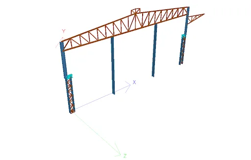
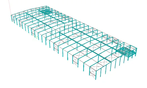
Shed designing with gantry
Structural steel connection design using RAM Staad connections
RAM connections software
Designing composite structures
Optimizing structural steel by pre-engineering
Job: Structural Engineer Jobs in the Design Wing of Consulting Firms, Power Plants
Higher education: Masters in Structural Engineering Masters in Industrial Structures PhD in Steel Connection Design PhD in Structural Steel Design
General upskill Firm understanding in working with STAAD.Pro, RAM Connections Knowledge on the design process followed for steel structures
01Analysis and Design of Industrial Structures using STAAD.Pro12 modules
Introduction to Industrial StructuresW01
In this session, you will learn
Steel structures in the industry
The stress-strain behaviour of structural steel
The properties of steel & shapes
Types of industrial structures
The key design factors
Types of structural systems in steel building
The general loads on industrial structures
Basic structural steel elements
Gravity and lateral load path
Structural redundancy
General design procedure
Iterative design process
Design of Tension MemberW02
In this session, you will learn
The types of tension members
The behaviour of tension member
Failure mode possibilities
The design strength of tension members
Factors affecting member strength
Shear Lag
Sections used for the tension member
Design of tension member
Design of Compression MemberW03
In this session, you will learn
The types of compression member
The behaviour of compression member
Failure mode possibilities
Sections used for compression member
The effective length of compression member
Design of compression member
Design of Built-up compression member
Design of Beams W04
In this session, you will learn about
Types of beam
The loads on Beam
Section classification
Lateral stability of beams
The effective length of beams
The design of laterally restrained beams
The design of laterally supported and unsupported beams
Design of purlins (Hot rolled)
Design of Plate GirderW05
In this session, you will learn
The types of sections
Elements of plate girder
General considerations
The proportioning of section
Preliminary sizing
Design of plate girder using IS 800:2007
Structural System of Industrial StructureW06
In this session, you will learn about the
Lateral load resisting system
Vertical load resisting system
Flooring system (Plating grating & Deck Beam)
Grating & chequered plate
Composite floor deck
Modelling of Structure in STAAD.ProW07
In this session, you will learn
Introduction to STAAD.Pro
Modelling nodes and beam element
Generating model geometry
Viewing geometry
Creating groups
Assigning properties
Assigning specification
Modelling tapered members
Assigning custom sections using user table
Member material specification
Modelling Finite elements
Modelling in physical modeller
Loading, Analysis and Design Procedure in STAAD.ProW08
In this session, you will learn
To create load cases
To apply self-weight
Modelling member loads and Floor loads
Application of load (vertical/lateral)
Modelling reference loads
Modelling of moving loads
Seismic load generation
Wind load generation
Application of design parameters
Performing simple analysis
Post-processing result interpretation
Analysis & design of Typical Steel Frame structure using STAAD. ProW09
In this session, you will learn
Input preparation
General modelling
Load & load calculations
Analysis of structure
The application of design parameters
Design of structure
The interpretation of post-processing results
Modelling , Analysis & Design of Industrial building (PEB) in STAAD.Pro.W10
In this session, you will learn about
Introduction to Pre-engineered building
the comparison of PEB over conventional building
Various components of PEB
General loads on PEB
Load combination as per IS 800: 2007 & AISC ASD
Input preparation
Load & Load calculations
Analysis of structure
The application of design parameters
Design of structure
Analysis & design of Pipe Rack structures using STAAD.ProW11
In this session, you will learn
Introduction to pipe racks
The components of pipe racks
The types of pipe racks
Loads on pipe racks
Load combination as per AISC, LRFD, ASD
Design criteria of structure
Case Study of pipe rack structure
Design of Foundation using STAAD.FoundationW12
In this session, you will learn
Introduction to STAAD.Foundation
Modelling supports
Modelling support loading
Importing information from STAAD.Pro
To design isolated footing
To design eccentric isolated footing
To design continuous footing
To design pile cap
To design soil supported mat foundation
To design pile-supported mat foundation
02Structural Steel Connection Design12 modules
Introduction to Connection Design and Bolted Connection TheoryW01
Introduction to Connection Design
Types of connections
Bolted Connections
Types of bolts
Load Transfer Mechanism
Bolted Connection Theory W02
Failure Mechanism of Bolted Connection
Specifications for Bolted Joints
Shear Strength of Bolts
Bearing Strength of Bolts
Tension Strength of Bolts
Welded connection Theory - Part 1W03
Welded Connection
Introduction
Types of Weld
Weld Symbols
Welded Connection Theory - Part 2W04
Welded Connection
Welding Procedure
Property of Weld Material
Specification of Weld
Welded Joint Vs Bolted Joint
Design of ConnectionsW05
Design of Connections
Introduction
General Procedure of Connection Design
Types of Connections
Shear Connections - Part 1W06
Shear Connections
Introduction
Single Angle Shear Connection
Double Angle Shear Connection
Shear Connections - Part 2W07
Shear Connections
Introduction
Fin Plate Connection
Extended End-Plate Connection
Beam-to-Beam Shear Connection
Moment Connections - Part 1W08
Moment Connections
Introduction
Bolted Flange Plate Connection
Welded Flange Plate Connection
Moment Connections - Part 2W09
Moment Connections
End Plate Moment Connection
Beam Splice Connection
Axial Forces Connections - Part 1W10
Axial Force Connections
Introduction to Base Plate
Pinned and Fixed Base Plate
Design Procedure for Pinned Base Plate
Design Procedure for Fixed Base Plate
Axial Forces Connections - Part 2W11
Introduction to Column Splice Connection
Bolted Cap and Base or End Plate Splices
Design of Gusset Plate and Tubular ConnectionsW12
Gusset Plate Connection
Tubular Connection
03Structural steel connections using RAM Connections10 modules
Concept of Steel Connections and Types of ConnectionsW01
A steel structure is an assembly of several members linked together. There are various types of connections depending on the method used for establishing contact. It is important for learners to understand the concepts in various types of steel connections.
This week will cover
Steel member joints like rigid joints, flexible joints, semi-rigid joints
Force flow through connections and concept of force distribution
Types of connections
Difference between shear and axial connection
Analysis and design of bolted connection & welded connection
Concept of Moment connection & Base PlateW02
Connections can be grouped based on the presence or absence of a moment. There is a flow of force through moment connections under loading conditions. It is important to understand the concept of moment connections to advance in this area.
RAM Connection is a software tool that can be used to virtually design, analyze and verify any steel connection. This can be used as a standalone tool or can be integrated with other software tools. It is essential to understand how such connections are designed and checked in RAM Connection.
Beams are the predominant load bearing members in a structure which are connected to several other components. It is important to understand how the RAM Connection software is used for designing various beam connections.
This week will cover
Clip angle beam column connection
Clip angle beam girder connection
Welded beam column connection
RAM Connection – Moment Connection Design (Part 1) W05
Moment connections involve the flow of bending moment forces between a beam and a column. Such connections are an integral part of building structures. It is important to understand the concept and design of moment connections.
This week will cover
Moment connections
Moment connection angle at beam column junction
RAM Connection – Moment Connection Design (Part 2)W06
End plates are used to connect a beam with another beam or with another structural component through welds and bolts. This is a moment connection that can be designed using RAM Connection. It is important to understand the concept of end plate connections for performing analysis on them.
This week will cover
Moment connections of end plate at the beam column junction
Moment connection with haunch
RAM Connection – Base Plate ConnectionsW07
Base plate connections involve a beam, steel plate and anchor connecting the plate to the foundations. Such connections are established using welds and bolts. It is important to understand the concept of base plate connections and their different types.
This week will cover
Base plates
Pinned type base plate connection
Fixed type uniaxial base plate connection
Fixed type biaxial base plate connection
RAM Connection – Splice Plate ConnectionsW08
Splice plate connections are established to provide continuity among the structural components in the building. A splice plate can be bolted or welded to the primary structure. To effectively design such connections using RAM Connection, it is important to understand its different types.
This week will cover
Bolted splice flange plate connection for beam splice
Bolted splice flange plate connection for columns splice
Bolted splice web plate connection for beam splice
Bolted splice web plate connection for columns splice
STAAD.Pro Connection Module (Part 1)W09
STAAD.Pro is one of the most widely used structural analysis and design software by civil engineers. This software tool allows the user to design and analyze a wide range of structures. To be able to perform all of this, one has to be familiar with the tool.
This week will cover
Connections module in STAAD.Pro
Method of design for welded connections
Method of design for moment connections
STAAD.Pro Connection Module (Part 2)W10
STAAD.Pro can be used to establish and verify a number of connections like end plate connections, base plate connections and splice joint connections. It is essential to understand the process flow involved in creating these connections.
This week will cover
Method of design for end plate connections
Design of base plates
Design of splice joints
04Design of Sheds with Gantry12 modules
Shelter Geometry W01
In this week, the following topics are covered.
Column spacing
Thumb rules for member sizing
Roof slope
Column orientation
Base plate configuration
Bracing pattern
Crane supporting arrangement
Crane vendor drawings study
Gantry GirdersW02
In this week, the following topics are covered.
Introduction
Different shapes/arrangements of girders
Different sections of rails
Loads
Vertical
Lateral
Longitudinal
Impact
IS code provisions
Design procedure
Roof TrussesW03
In this week, the following topics are covered.
Introduction
Selection of type of truss
Spacing of truss
Panel layout
Loads on roof truss
Deflection of truss
Connection
Bracing of trust
Solved examples
STAAD ModellingW04
In this week, the following topics are covered.
Shelter modelling in STAAD
Assigning properties to members
Assigning specifications to members
Assigning supports
Redefining incidences
Renumbering of nodes and members
STAAD ModellingW05
In this week, the following topics are covered.
Dead loads
Indian code provisions
Member self-weight
Connection weight
Purlin and cladding runner weight
Cladding weight
Roof sheeting weight
Live loads
Indian code provisions
Live loads on crane platforms
Live loads on the roof
Collateral loads/MEP loads
Crane Loads
Vertical loads
Horizontal loads
Impact loads
Wind Load Calculations using Indian CodesW06
In this week, the following topics are covered.
Wind loads on walls
Open shelter
Partially open shelter
Closed shelter
Wind loads on roofs
Open shelter
Partially open shelter
Closed shelter
Load Application in STAAD
Analysis and Design W07
In this week, the following topics are covered.
Creating strength and service load combinations
Analysis and design
Design parameters
Checking analysis results
Design of runner beams
Design of Beams and ColumnsW08
In this week, the following topics are covered.
Checking SFD and BMD in STAAD.Pro
Comparing with manual beam design
Comparing with manual column Design
Base Plate DesignW09
In this week, the following topics are covered.
Introduction to base plates
Types of base plates
Design procedure
Design of handbook using AISC design guide
Special PublicationsW10
In this week, the following topics are covered.
Steel structure with portal frames with cranes
Steel structures with steel roof trusses with and without cranes
Design Drawing PreparationW11
In this week, the following topics are covered.
How to prepare design drawings?
Scaling of design drawings
Drawing sizes to be used
Layout of design drawings
General notes to be covered in design drawings
Design Report Preparation W12
In this week, the following topics are covered.
How to prepare a design report for submission to a client?
Points to be covered in the design report
05Basic Structural Engineering Concepts of Industrial Structures6 modules
Overview of Industrial StructuresW01
Major Types of Industries (Power, O&G, Steel, Pharmaceutical, FMCG, Manufacturing, Infrastructure, Commercial Structures, etc.)
Types of Structures in Each Industry Based on their Use
Stages of a Project's Execution: Proposal, Basic Engineering, and Detail Engineering
Different Types of Engineering Disciplines Involved in an Industrial Project and their Roles and Responsibilities
Structural Engineering in Industrial ProjectsW02
Introduction to Various Industrial Standards (IS, BS, AISC, ACI, PIP, and API)
Different Types of Materials for Construction
How the Materials are Named/Defined
Different Types of Loads in Industrial Structures (Dead, Live, Wind, Seismic, Anchor, Friction, Dynamic Loads, Temperature)
Concept of Developing General Arrangement Drawings
Concept of Developing Detail Drawings
Purpose of Fabrication Drawings
Purpose of the Bar Bending Schedule
Brief Idea of Design Basis, Design Criteria, Vendor Documents, Prebid Activities, etc.
Pipe Racks, Pipe bridges and Pipe SleepersW03
Introduction to Pipe Racks
Typical Size of a Pipe Rack
Structural Arrangement of Pipe Racks
Concept Behind the Selection of Material for Construction
Types of Loads on a Piperack
Concept of Structural Arrangement to Handle Various Loads
Design Concept of Various Components
Roles and Responsibilities of Various Disciplines (Electrical, Mechanical, Instrumentation, etc.)
Constructability via Design Approach
Equipment Supporting Structures and Introduction to Modular StructuresW04
Brief Introduction
Input for Design
Material of Construction
Analysis and Design
Design Loads
Types of Foundations
Types of Modular Structures
Typical Size of a Modular Structure
Basic Design Criteria for Modular Structures
Concept Behind the Selection of Material for Construction
Types of Loads in Modular Structures
Concept of Structural Arrangement to Handle Various Loads
Design Concept of Various Components
Constructability
A Brief Description of Lifting Analysis
Example of Modular Structure Design
Substation and Control BuildingsW05
Introduction to Substation and Control Buildings
Typical Size of a Substations/Control Building
Concept Behind the Selection of Material for Construction
Types of Loads in a Substations/Control Building
Concept of Structural Arrangement to Handle Various Loads
Design Concept of Various Components
Roles and Responsibility of Various Disciplines (Electrical, Mechanical, Instrumentation, etc.)
Constructability of a Composite Building: RCC and Steel Structure
Pre-Engineered Metal Buildings (PEMBs)W06
Introduction to Pre-Engineered Metal Buildings (PEMBs)
Materials, Layout, and Components of PEMB
Types of PEMB
Adaptability of the PEMB Concept Over Other Construction Options
Types of Loads on PEMBs
Monorail, Gantry Girder Placement, and Support System
Foundation Design of PEMB, Load Transfer Due to Equipment
Roles and Responsibilities of Various Disciplines (Electrical, Mechanical, Instrumentation, etc.)
Constructability
06Structural Optimization of steel structures by Pre-Engineering12 modules
Introduction to Steel Buildings & PEBs W01
In this week, the following topics are covered.
Introduction
Anatomy of steel buildings
Materials used
Standard codes & manuals
Basic ConceptsW02
In this week, the following topics are covered.
Introduction to steel design
Refreshment of concepts
Planning a PEBW03
In this week, the following topics are covered.
Framing
Support system
Lateral stability system
Analysis methodology
Brief to Standards of DesignW04
In this week, the following topics are covered.
Load Resistance Factor Design Vs Allowable Stress Design
Important provisions from MBMA codes, AISC codes & IS codes considered for design
Load Calculations W05
In this week, the following topics are covered.
Load calculations
Dead
Live
Wind
Load combinations as per MBMA
Analysis of Main FrameW06
In this week, the following topics are covered.
Property assignment to frame for preliminary analysis
Behavioural study of a typical frame-BMD, SFD, Deflections
Manual Comparison
Self-check of analysis results
Design of Main FrameW07
In this week, the following topics are covered.
Choosing element lengths for splice
Applying design parameters on STAAD.Pro
Checking utilization ratios
Tapering of Members for Maximum UtilizationW08
In this week, the following topics are covered.
Tapering techniques for maximum utilization
Checking web buckling & bearing-requirement of stiffeners
Serviceability verification
Design of Gable End Frame & Secondary MembersW09
In this week, the following topics are covered.
Design of gable end frame
Design of purlins, bracings and flange bracings
Verifying 2D Vs 3D DesignW10
In this week, the following topics are covered.
Verifying design results
Extracting forces for connection design
Extracting reactions for foundation design
Design of ConnectionsW11
In this week, the following topic is covered.
Typical connection/splice design for a frame using IS code
Preparing BOQ and BIM inputsW12
In this week, the following topics are covered.
Preparing Bill of Quantity
Providing inputs to BIM - Hand sketches
Tips for checking drawings
07Reinforced Cement Concrete Design12 modules
Structural systems, Properties of concrete & Properties of reinforcing steelW01
Objectives of structural design
Example of structural systems (different types of floor systems, vertical and lateral framing systems etc.)
Design codes
Basics of concrete mix proportions and unit weight.
Unconfined compressive strength of concrete (cylinder & cube)
Stress-strain curve for concrete and its characteristics modified Hognestad parabola)
Concrete stress-strain curve per IS 456:2000
Confined strength of concrete (overview)
Characteristic strength of concrete, the tensile strength of concrete
Shrinkage & creep
Properties of steel (stress v/s strain, Fe250/Fe415/Fe500)
Design Philosophies & Beam in Flexure (analysis) W02
Preview into WSM, Strength Design (ULM) and Limit State Design (LSD)
Two Limit States (serviceability & strength)
Characteristic loads and load safety factor
Design material strength
Building frame example [Load distribution from slab – beam-column – foundation]
Slabs in building
One-way slabs (behaviour and structural analysis)
Theory of flexure
Concept of the neutral axis
Failure modes of RC section (under-reinforced, over-reinforced & balanced section)
Moment of resistance
One-way slabs & Two-way slabsW03
Structural analysis and design of one-way slab
Reinforcement detailing for one-way slabs
Introduction to two-way slabs
Difference between one-way & two-way slabs
Analysis of two-way slabs
Effective span for two-way slabs
Design example (two-way slabs)
Reinforcement detailing in two-way slabs
Beams in FlexureW04
Introduction to reinforced concrete beams
Moment of resistance
Concept of flanged beams in buildings
Analysis of under-reinforced rectangular beams
Analysis of over-reinforced rectangular beams
Flanged beams (effective width and other
characteristics)
Analysis of flanged beams in flexure
Limiting percentage of steel in beams
Beams in FlexureW05
Analysis of T-Beam (design example)
Concept of doubly reinforced rectangular beam
Analysis of doubly reinforced beam
Beams in Flexure, Bond, development length and anchorage lengthW06
Structural analysis of beam in the building frame
Design of singly reinforced beam in the building frame
Reinforcement detailing of beams
Bond strength of concrete
Development length and anchorage length
ShearW07
Principal stress in beams
Modes of cracking
Shear transfer mechanism
Effect of reinforcement on shear failure
Nominal shear stress in the beam
Critical section for one-way shear
Shear strength without shear reinforcement
Shear strength of the slab
Shear strength with shear reinforcement
Reinforcement detailing of shear reinforcement
Design example
Torsion & Deep BeamsW08
Torsion in structural members (compatibility torsion and equilibrium torsion)
Torsional reinforcement provisions per IS code
Torsional reinforcement detailing
Design example
Introduction to deep beams and design example
ColumnsW09
Tied columns and spiral column
Loading on columns
The effective length of the column (braced & unbraced length)
Effective length per IS 456
Slender and short columns, slenderness limits
Reinforcement detailing of columns
The design strength of short column under pure axial load
ColumnsW10
Short column subjected to axial load and uniaxial moment
Strain profile under axial load and varying eccentricities
Introduction to P-M interaction curve
Possible modes of failure of column
Generating P-M interaction curve (equations and design example)
Design of column subjected to axial load and uniaxial moment
Design of column subjected to axial load and biaxial moment
Use of design aids (SP 16) for column design
FoundationsW11
Types of foundation (isolated, raft, combined, wall)
Bearing pressure under footing (due to axial load, axial load and uniaxial moment)
Design considerations (Bearing pressure, one-way shear, two-way shear and flexure)
Transfer of forces at column base: Bearing of concrete
Combined foundation (introduction and need for combined foundation)
Analysis of combined foundation
Design example: Combined foundation
08Structural Analysis and Design of Composite Structures using ETABS14 modules
Structural Systems for Tall Buildings (Part 1)W01
This week will cover
Basics of tall buildings
Tallest buildings in the world (as of 2020)
Loadings and supports
Structural mechanics concepts
Structural elements and their behaviour
Structural systems and their classification
Structural Systems for Tall Buildings (Part 2)W02
This week will cover
Structural systems and their behaviour
Comparative study of structural systems
Shanghai Tower – structural framing & challenges
Taipei 101 – structural framing & challenges
p-δ analysis
Loads on Tall Buildings W03
This week will cover
Gravity loads
Load paths
Modelling of structure
Wind loads as per IS 875: 2015 (Part 3)
Wind load estimation & application in ETABS
Earthquake loads as per IS 1893: 2016
Seismic load estimation & application in ETABS
Design philosophy in wind & seismic loads
Modal Analysis of Tall buildingsW04
This week will cover
Underlying Physics
D'alembert's Principle
Equation of Motion
Modal Analysis
Influence of Modal Response
Idealized Model – SDOF Structure
Structural Analysis and Design of Concrete Structures (Part 1)W05
This week will cover
Structural actions
Concrete & its key properties
Characteristic strength
Stress-strain curves
Creep & shrinkage
Corrosion
Design methodology
Limit state of design
Load combinations
Structural Analysis and Design of Concrete Structures (Part 2)W06
This week will cover
Type of slab & its function
One-way vs Two-way slabs
Slab design & detailing
Beam types
Beam analysis & design
Column classification
Column analysis & design
Wall design
Structural Analysis and Design of Steel Structures (Part 1)W07
This week will cover
Steel vs Concrete comparative study
Structural steel sections
Section classification
Allowable stress design
Limit state design
Design flow chart
Design of tension members
Failure modes and strength estimation
Structural Analysis And Design Of Steel Structures (Part 2)W08
This week will cover
Design of compression member
Euler buckling criteria
Flexural buckling
Torsional-Flexural buckling
Design of beams
Deflection criteria for the beams
Bolted connection
Welded connection
Fundamentals of Composite Structures (Part 1)W09
This week will cover
Composite structures
Practical applications
Key advantages
Composite deck slab
Design philosophy
Construction of composite deck slab
Advantages of composite deck slab
Connection details
Fundamentals to Composite Structures (Part 2)W10
This week will cover
Composite beam philosophy
Load transfer
Design criteria
Prefabricated composite beams
Composite coupling beams
Composite columns
Load capacity of composite columns
Composite connection
Composite wall
Software advances
Framing Plan for Composite Deck Slab (Part 1)W11
This week will cover
Composite deck slabs
Various available profiles
Design parameters
Floor framing options
Manual calculations
Deck sizing and selection
Modelling and analysis in ETABS
Analysis of composite beams
Design of composite beam
Framing Plan for Composite Deck Slab (Part 2)W12
This week will cover
Construction details of composite slab
Shear connectors
Shear studs and their load transfer mechanism
Shear resistance of the studs
Floor vibration
Cambering
Heat cambering vs cold cambering
Scheduling of construction
Structural Design of Composite Buildings using ETABS (Part 1)W13
This week will cover
Study of an apartment floor plan and its occupancy
Schematizing the structure with a dual system
Selection of codes & Materials in ETABS
Defining the steel beam member and Composite column in ETABS
Structural Design of Composite Building using ETABS (Part 2)W14
This week will cover
Definition of composite deck slabs in ETABS
Overview of Seismic load factors from IS-1893 and its application in ETABS
Overview of Wind load factors from IS-875 and its application in ETABS
Analysis and design verification of Composite columns & Steel beams in ETABS
Industry projects
15 projects you'll ship.
Our projects are designed by experts in the industry to reflect industry standards. By working through our projects, Learners will gain a practical understanding of what they will take on at a larger-scale in the industry. In total, there are 15 Projects that are available in this program.
Analysis and Design of Industrial Structures using STAAD.Pro
Proposed Coil Center (Industrial Building) with Crane Load at Chennai using STAAD. Pro
In this project, A trussed roof structure of 30m span is analyzed and designed including crane load using STAAD.Pro and the complete project report should be created for the same.
Analysis and Design of Industrial Structures using STAAD.Pro
Proposed PEB warehouse (Industrial Building) at Coimbatore using STAAD. Pro
In this project, the student is asked to design a PEB for a proposed warehouse using STAAD.Pro along with the complete project report. From the above two projects, students come to…
Structural Steel Connection Design
Beam to Beam Shear Connection
During this project work, the students will design a Beam to Beam Shear Connection with a double-angle cleat. This will help students to understand the concepts in depth with which…
Structural Steel Connection Design
Design of Connections for a Factory Building
This project will give complete insight on how to design the following for a factory building Secondary beam to primary beam connection – Fin plate shear connection Primary b…
Structural Analysis and Design of Composite Structures using ETABS
Modelling, Analysis, & Design of Tall Buildings in ETABS
In this project, learners need to model a commercial structure using ETABS with given dimensions. They will also have to perform load estimation and application. In addition to thi…
Structural Analysis and Design of Composite Structures using ETABS
Modelling, Analysis & Design Of Composite Structures in ComFlor & ETABS
In this project, learners need to model a composite deck slab frame by preparing a framing plan and selecting the floor deck type using ComFlor & ETABS with given dimensions. A…
Structural Optimization of steel structures by Pre-Engineering
Single Span PEB Design using STAAD.Pro
PEB is called as Pre-Engineered building. A PEB is basically a building which is assembled using parts which are manufactured separately. In this project, a single span PEB is desi…
Structural Optimization of steel structures by Pre-Engineering
Double Span PEB Design using STAAD
PEB is called as Pre-Engineered building. A PEB is basically a building which is assembled using parts which are manufactured separately. In this project, a double span PEB is desi…
Structural steel connections using RAM Connections
Design and Optimize Base Plate Connections
Learners will have to design and optimize a typical shear, moment, and splice joints connection using RAM Connections for the given structure modelled in STAAD.Pro.
Structural steel connections using RAM Connections
Design and Optimize a Typical Shear, Moment, and Splice Joint Connection in STAAD Connection Module
Learners are required to design and optimize a typical shear, moment, and splice joint connection in STAAD Connection module for the given structure modelled in STAAD.Pro.
Reinforced Cement Concrete Design
Analysis and design of slab and beam system using IS 456-2000
In this project, the students will be asked to design and analyse a slab and beam using IS 456-2000. They will also design and detail the reinforcement in the slab and beam.
Reinforced Cement Concrete Design
Design of beams and slabs for shear and Design of columns for compression and uniaxial bending using SP16 charts
In this project, the same framing layout of project 1 is considered. It includes the design of beams and slabs for shear, the design of columns for compression and uniaxial bending…
+ 3 more projects in the full syllabus
Learner stories
Learners from Skill-Lync's civil programs. In their own words.
Video stories from learners of related civil programs, from Skill-Lync's YouTube channel.
KrishnaSite Engineer, Cochin RefineryPG Program in High Rise Building Design & AnalysisYaminiBentleyPGP in High-Rise Building Design & AnalysisVinayStructural Design EngineerPG Program in Bridge Design and AnalysisShubamPrimavera Engineer, GKC ConsultantsPGP in High-Rise Building Design & AnalysisKrishnatejaCivil Drafter, ACE ConsultantPG Program in High-Rise Building Design and Analysis
Guide
Steel structure design, explained.
by the Skill-Lync team
What does a PG program in steel structures teach, and in what order?
It teaches you to analyse, design and connect the steel frames of industrial buildings. You start with members to IS 800:2007, move to STAAD.Pro models of sheds, pre-engineered buildings and pipe racks, then bolted and welded connections and crane sheds. RCC design and composite floors in ETABS complete it. The program runs 48 weeks, online.
The syllabus, in order:
Analysis and Design of Industrial Structures using STAAD.Pro (59 lessons, about 28 hours). Tension and compression members, beams and plate girders by hand, then STAAD.Pro models of a steel frame, a PEB and a pipe rack, and footings in STAAD.Foundation. A PEB (pre-engineered building) is a factory-made steel frame whose members are tapered, deep where the bending is large and slim where it is small. A pipe rack is the steel frame that carries pipes and cables across a plant.
Structural Steel Connection Design (45 lessons, about 21 hours). Bolt and weld theory, then shear, moment and axial connections, base plates, splices and gusset plates.
Structural steel connections using RAM Connections (35 lessons, about 17 hours). The same joints designed and checked in RAM Connection and in the STAAD.Pro connection module.
Design of Sheds with Gantry (48 lessons, about 22 hours). Shed geometry, gantry girders, roof trusses, dead, live, crane and wind loads to Indian codes, base plates, design drawings and a design report.
Basic Structural Engineering Concepts of Industrial Structures (12 lessons, about 4 hours). How an industrial project runs, pipe racks, equipment supports, modular structures, substations and pre-engineered metal buildings.
Structural Optimization of Steel Structures by Pre-Engineering. PEB frames to MBMA, AISC and IS provisions, tapering, gable frames, purlins and a bill of quantities.
Reinforced Cement Concrete Design (69 lessons, about 32 hours). Slabs, beams, columns and footings to IS 456.
Structural Analysis and Design of Composite Structures using ETABS. Tall-building systems, IS 875 wind and IS 1893 seismic loads in ETABS, and composite deck slabs.
Three lessons from each of the first five courses are free on Grow. The answers below use them, starting with the RAM Connections lessons on bolt checks.
How do you check a bolt for shear and bearing under IS 800:2007? A worked example
Work out two capacities and use the smaller one. Shear capacity (clause 10.3.3) is the bolt being cut across, like paper in scissors. Bearing capacity (clause 10.3.4) is the bolt crushing the edge of its hole. An M20 grade 4.6 bolt in an 8 mm plate gives 45.3 kN in shear and 79.5 kN in bearing, so shear governs.
This is the check the free RAM Connections lesson walks through, clause by clause. The inputs:
An M20 bolt, grade 4.6. The free connection lesson explains the grade: 4 × 100 = 400 MPa ultimate strength, and 0.6 × 400 = 240 MPa yield.
One shear plane, passing through the threads, as in two lapped plates.
An 8 mm E250 plate, ultimate strength fu = 410 MPa (IS 800 Table 1).
A 22 mm hole: Table 19 adds 2 mm to a 20 mm bolt. End distance e = 40 mm, pitch p = 60 mm.
Spacing first. Clause 10.2.4.2 asks for an end or edge distance of at least 1.5 × 22 = 33 mm for machine-cut edges, or 1.7 × 22 = 37.4 mm for sheared edges. Clause 10.2.2 sets the minimum pitch at 2.5 × 20 = 50 mm. 40 mm and 60 mm pass.
Shear. The threads sit in the shear plane, so use the area at the threads. The lesson takes it as 0.78 × the shank area, 245 mm². With γmb = 1.25 (Table 5):
Vdsb=3fub⋅γmbAnb
400/√3 × 245/1.25 = 45.3 kN.
Bearing.
Vdpb=γmb2.5kbdtfu
kb is the smallest of e/3d0 = 0.606, p/3d0−0.25 = 0.659, fub/fu = 0.976 and 1.0. So kb = 0.606: the bolt sits close to the end of the plate, and the end distance limits it. 2.5 × 0.606 × 20 × 8 × 410/1.25 = 79.5 kN. The RAM report reviewed in the lesson shows the same kb, 0.606.
Result. Each bolt is worth 45.3 kN. A joint carrying a factored 150 kN needs 150/45.3 = 3.31, so 4 bolts.
Now try grade 8.8. Above 16 mm diameter, Table 1 gives it fub = 830 MPa. Shear rises to 93.9 kN, but bearing stays at 79.5 kN because kb is still 0.606. Bearing now governs and 2 bolts carry the 150 kN. A stronger bolt pays off only with a thicker plate or a longer end distance. The lesson also lists block tearing (6.4.1) and combined shear and tension (10.3.6). One caution: the voice-over reads the second kb term as minus 2.25. The code says 0.25.
What is the difference between bearing bolts and friction grip (HSFG) bolts?
A bearing bolt lets the plates slip until the hole edges press on it, so the bolt carries load in shear and bearing. A high strength friction grip (HSFG) bolt is tightened so hard that it clamps the plates together. Friction between them carries the load, like books pressed tight in a stack, and nothing slips.
The free Structural Steel Connection Design lessons cover both. Ordinary (black) bolts are grade 4.6 and suit purlins, bracing and roof trusses under steady loads. The lesson says not to use them under impact, vibration or fatigue, such as crane braking or machine skids. HSFG bolts are classes 8.8 and 10.9, made to IS 3757. The contact surfaces must be free of mill scale, rust, paint and grease. Class 8.8 may be hot-dip galvanized, but class 10.9 should not be.
Worked example: the same M20 8.8 bolt as a friction bolt. IS 800:2007 clause 10.4.3:
Vdsf=γmfμfneKhFo
Fo is the proof load, the tension left in the bolt after tightening: 0.70fubAnb = 0.70 × 830 × 245 = 142.3 kN.
μf is the slip factor, the friction coefficient of the clamped plate faces (Table 20). ne = 1 friction interface. Kh = 1.0 for standard clearance holes. γmf = 1.25 when slip is checked at factored loads.
Surfaces blasted with shot or grit, loose rust removed, μf = 0.50: 56.9 kN per bolt, so 3 bolts.
Two things follow. Surface preparation alone saves a bolt here. And a friction bolt carries less than the same bolt in bearing (79.5 kN), so you pay for "no slip". Use it where slip matters, such as crane girders, vibrating machinery and moment joints that must stay rigid.
How do you lay out a steel shed before detailed design? A worked example
Fix the geometry with thumb rules, then put loads on it. The free Design of Sheds with Gantry lessons suggest columns 6 to 7.5 m apart, a roof slope of about 1 in 10 and a truss depth of span/10 to span/12. A 74 m × 16 m shed then gets 10 bays of 7.4 m, or 11 frames.
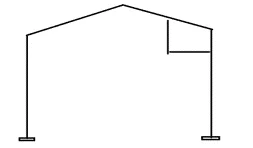
First, the parts. A portal frame is two columns and a sloping rafter joined rigidly, like an upside-down U with a pitched top. Purlins are light beams, channels or cold-formed Z sections, that run from frame to frame and carry the roof sheets. Side girts do the same for wall sheeting. Bracing keeps the frames from leaning. A gantry is the bridge-like crane structure, and a corbel or bracket on each column carries the gantry girder it runs on.
Take the lesson's sample STAAD model: a pre-engineered warehouse with a 10 t crane, about 74 m long, with main frames about 16 m wide.
Bays. 74/7.5 = 9.9, so 10 equal bays of 7.4 m and 11 frames. Keep bays equal: the lesson's 50 m building at 5 m needs 11 columns, while mixed 5, 7 and 8 m bays mean rework in fabrication and erection. Service needs come first, though. A heavy-vehicle service shed in the lesson uses bays of about 10 m so trucks can turn.
Roof slope. 1 in 10 is 5.71°, a 0.8 m rise from eaves to ridge over the 8 m half-span. Slope also cuts deflection: in the lesson's 2D STAAD comparison, the sloped frame deflects 97 mm against 120 mm for a flat one, about a fifth less.
Truss option. If the roof is a truss, its depth is 16/10 = 1.6 m to 16/12 = 1.33 m.
Roof live load. IS 875 (Part 2) Table 2 gives 0.75 kN/m² on plan for roofs up to 10° with no access except for maintenance. Each interior frame collects a 7.4 m strip: 0.75 × 7.4 = 5.55 kN/m along the rafter, or 88.8 kN per frame.
Dead load (sheets, purlins, self-weight), crane loads and wind to IS 875 (Part 3) go on top of this, in weeks 5 and 6 of the course. You can try a rough build-up in the steel structure load calculator.
How do you work out gantry girder loads for an EOT crane? A worked example
Start from the crane maker's maximum static wheel load, then add the IS 875 (Part 2) allowances. For an electric overhead travelling (EOT) crane: plus 25% on vertical wheel loads for impact, 5% of crab plus lifted load sideways, and 5% of the wheel loads along the rail. A 60 kN wheel becomes 75 kN.
A gantry girder is the beam along each column line that carries the crane rail. The crab is the trolley with the hoist that runs across the crane bridge. The free sheds lesson shows how to read the crane maker's vendor drawing for wheel loads, wheel base and crane span. These inputs are assumed values for illustration: a 10 t crane (lifted load 100 kN), crab 20 kN, maximum static wheel load 60 kN, two wheels per rail 3.0 m apart, girder span 7.4 m.
Lateral surge, from the crab starting and stopping: 5% × (20 + 100) = 6 kN per rail, or 3 kN per wheel, acting at rail level. Cranes with a rigid mast, such as soaker and stripper cranes, take 10%.
Longitudinal, from the crane braking: 5% × (2 × 60) = 6 kN per rail.
Maximum moment. With two equal moving loads P a distance a apart, the peak sits under one wheel when midspan lies halfway between that wheel and the resultant:
Mmax=2LP(L−a/2)2
75 × 5.9²/14.8 = 176.4 kN·m, against 138.8 kN·m for a single wheel at midspan. The formula holds while a is less than about 0.586 L.
The 3 kN surge loads give 7.06 kN·m about the weak axis. The top flange carries most of it, which is why heavier cranes get a channel capping the top flange or a horizontal truss, as the free lesson shows. For stiffness, IS 800:2007 Table 6 limits vertical deflection to span/750 = 9.9 mm for EOT cranes up to 50 t, and lateral deflection to span/400 = 18.5 mm. These are unfactored loads. Load factors and crane load combinations are applied before the strength checks, and week 2 of the sheds course covers gantry girder loads, the IS code provisions and the design procedure.
Can you trust a RAM Connection or STAAD.Pro design report?
Use it, but read it line by line. The free RAM Connections lesson reviews a report for a bolted beam-to-column shear joint. It checks edge distances, pitch, bolt shear, bearing, block tearing, plate shear and angle bending, each with its IS 800 clause and a ratio of demand to capacity. No ratio may exceed 1.0.
The global critical strength ratio is the largest of those ratios. It shows which check governs. If any ratio passes 1.0, change the input: more bolts, a thicker cleat or a larger end distance.
Some checks are not in IS 800. The lesson points out that the connector-length and angle prying checks come from BS EN 1993 and other references. Know which code each line uses before you sign it.
Hand-check one line, such as the bolt bearing value worked out above. The lesson's report gives the same kb of 0.606.
The software in the program: STAAD.Pro for frames, sheds, PEBs and pipe racks; STAAD.Foundation for footings; RAM Connection and the STAAD.Pro connection module for joints; ETABS and ComFlor for composite floors. Compare the options in the structural design course comparison.
Do steel structure design skills lead to jobs?
Yes, mostly as structural design engineers or steel detailers, but our own data here is thin. As of 19 Nov 2026, Skill-Lync has no placement records filed under this program. Of 378 records in the civil domain, 26 have "structural" or "steel structure" in the job title, with a median of ₹4.2 LPA.
Structural roles: all 26 disclosed pay, from ₹1.8 to ₹10 LPA. The 12 freshers had a median of ₹2.85 LPA, and the 13 with experience ₹5.25 LPA. Employers include Eversendai, Hitachi Energy (a connection design role), RITES and Freyssinet Menard. The records run from 2021 to 2025.
Detailers: 69 records have "detailer" in the job title, 59 of them at DGS Technical Services, with a median of ₹2.4 LPA. A detailer turns the design into fabrication drawings of every plate and bolt. It is a common way in, though this program teaches design drawings rather than detailing software such as Tekla.
These figures come from Skill-Lync's placement records (n = 3,905). They are a self-reported learner sample, mostly 2021 to 2023 starting offers, so treat small groups with care. See civil engineer salaries for a wider view.
Which Skill-Lync steel structures course fits you?
Course
Length
Projects
Tools
Fee
PG Program in Steel Structures (this page)48 weeks: members, connections, crane sheds, PEB, ETABS
The program runs 48 weeks, online. Its syllabus covers industrial structures in STAAD.Pro, structural steel connection design, connections in RAM Connections, sheds with gantry, basic concepts of industrial structures, pre-engineered steel buildings, RCC design, and composite structures in ETABS.
Is there any pre-requisite for joining this course?
This course is highly suitable for students who have basic knowledge and belong to civil engineering.
Will I be able to get an e-verification after completing the course?
Yes. The Premium plan includes a personalised page to showcase your projects and certifications, which you can share on sites such as LinkedIn.
Will I get any support if I have doubts?
Yes. The Premium plan lists support over mail and telephone, and live individual and group sessions to resolve queries. Individual sessions are scheduled by engineer availability.
What will be the mode of delivery of the course?
The program is delivered 100% online.
Does Skill-Lync offer any community forums where I can get support?
The Premium plan lists live group sessions with experts, plus mail and telephone support. A separate community forum is not among the listed plan features, so ask a counsellor what your batch gets.
Is this course useful for me if I want to get a job?
It can help, but our own data is thin. As of 19 Nov 2026, Skill-Lync has no placement records filed under this program. Of 378 records in the civil domain, 26 have "structural" or "steel structure" in the job title, with a median of ₹4.2 LPA (self-reported, 2021 to 2025). The program teaches STAAD.Pro, RAM Connection and ETABS against IS 800, IS 875 and IS 456.
Does the course include any project work?
Yes. Listed projects include a coil centre with crane load at Chennai and a PEB warehouse at Coimbatore in STAAD.Pro, connections for a factory building, base plate connections and shear, moment and splice joints in the STAAD connection module, single- and double-span PEB designs, a shelter modelled from architectural drawings, a composite structure in ComFlor and ETABS, and RCC slab, beam and column designs to IS 456.