Geometry Pattern in Solidworks
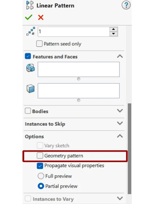
When a linear pattern option is used to multiply the instances, a geometry pattern option is available in the options section as shown in the below picture.
 Navin Baskar·25 May 2023·2 min read
Geometry Pattern in Solidworks
What is the linear pattern?
A linear pattern is an option that is present in Solidworks, which creates duplicate instances of features/bodies along linear paths.
When a linear pattern option is used to multiply the instances, a geometry pattern option is available in the options section, as shown in the below picture.
What is a geometry pattern?
When the geometry pattern option is enabled, the exact geometry of the parent feature gets multiplied.
Advantages of geometry pattern:
- Instances are multiplied without solving at each instance
- When the geometry pattern option is enabled, it speeds up the creation and rebuilding of the pattern.
What is the difference between when the geometry pattern option is enabled and disabled?
Let’s take the example of creating a linear pattern.
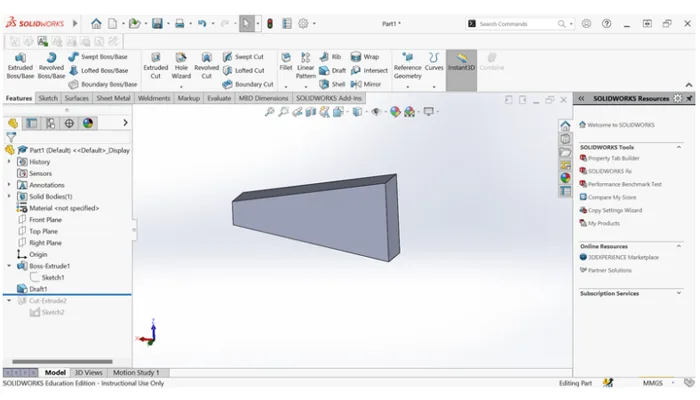
Create a body as shown in the below picture.
Create a circle on the Top Face.
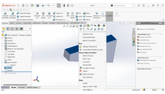
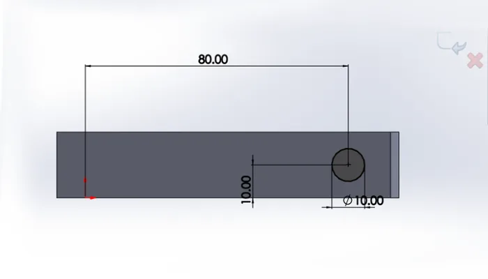
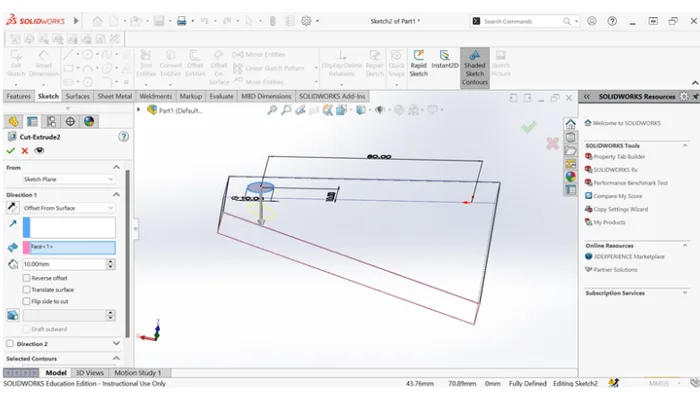
Select Cut-Extrude using offset from the surface as shown below.
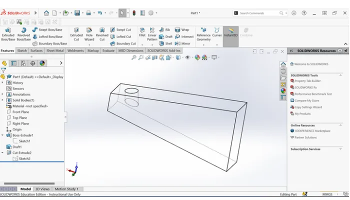
After the Cut-Extrude feature, the model looks like the below figure.
Now create a Linear pattern using the below edge for Direction 1 and in the feature select the Cut-Extrude.
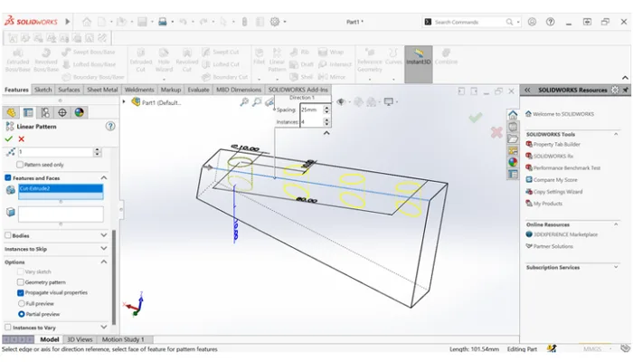
When scrolled down under the option ‘Geometry pattern’ option is available.
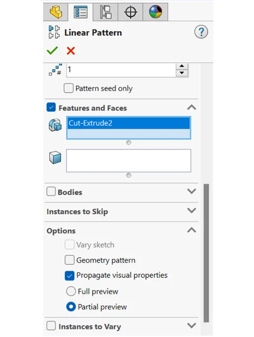
1) When the geometry option is enabled:
When the geometry pattern option is enabled, the Cut-Extrude feature is multiplied at a given spacing distance. The feature is multiplied like the exact geometry of the Cut-Extrude feature.
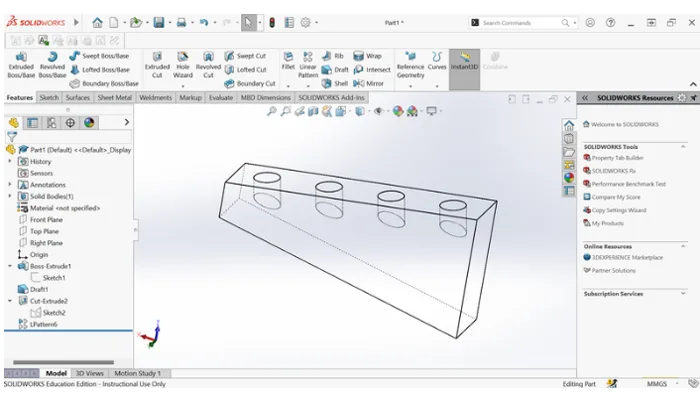
The pattern is observed as shown in the below picture.
Here, you can observe the pattern is taking the reference of the Cut-Extrude feature. It simply multiplies the instances. The offset distance is 10 mm for the first, but not for the instances.
2) When the geometry option is disabled:
When the geometry pattern option is disabled, the Cut-Extrude feature is multiplied at a given spacing distance. The instances get multiplied by solving and taking references of the parent.
The pattern is observed as shown in the below picture.
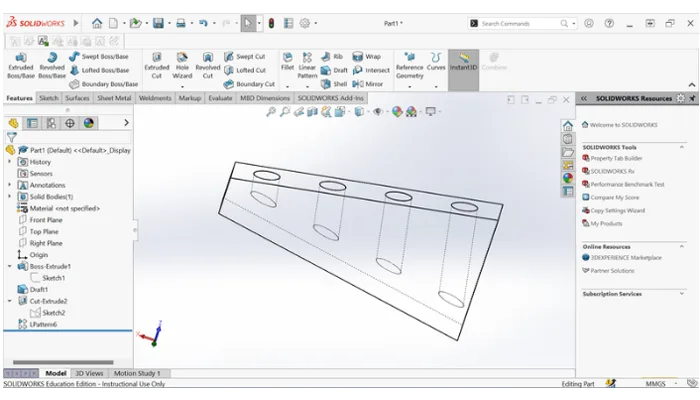
Here, you can observe the instances are taking the reference as a face for all the instances. Since the top face is taken reference for the parent, children also take the reference as the face. So the offset distance of 10 mm in Cut-Extrude will be the same in all instances w.r.t the face.
Conclusion: In this article, you have learned how the geometry pattern option works in the linear pattern by taking any references and advantages of the geometry pattern when rebuilding is done.