Menu


Modified on
Simulating flow through backward facing step

Skill-Lync
Studying flow behavior through various structures is an important subject of mechanical engineering. When fluids flow through different geometries, they exhibit different velocity, pressure, and flow properties. We have decided to simulate flow through a backward-facing step to study the flow of fluids through geometries that have sudden-changing shapes.
Main Objective
In this project, we are going to:
- Analyze and simulate flow through a backward-facing step
- Plot contours for velocity and pressure to visualize how to flow separation takes place
The objective is to understand how different quantities like velocity, pressure behave due to the sudden step.
Steps to be done:
- Creating geometry
- Setting up case
- Boundary Flagging
- Assigning boundary conditions
- Assigning regions
- Post-processing the results.
- Plot the results
Creating Geometry:
Software used: Converge Studio
We can create a backward step in any CAD software like SolidWorks and import them into CONVERGE or we can create a geometry in Converge directly. In this project, we have created a geometry directly in CONVERGE.

Setting up the case:
We will then set up the case in CONVERGE Studio by flagging the boundary and assigning boundary conditions and initial conditions.
Boundary flagging:
In this step, we take triangular structures and flag them together as boundaries which are marked with different colours. This is done so that the boundary conditions can be assigned to each triangular structure.

Assigning conditions:
Once the boundaries have been flagged, we assign the different boundary conditions for the flow to take place within the geometry. In the series of snapshots below, you can see the various boundary conditions that are assigned to the geometry:
Inflow boundary conditions:

Outflow boundary conditions:

Front and back walls:
The front and back walls of the geometry are 2 dimensional since this is a 2 D simulation.

Top and bottom walls:

Assigning regions:
Here, we will put the planes together and assign initial conditions in the volumetric region.
Just like we group triangles to boundaries, we can group the boundaries to define individual volumes. These volumes are called regions in Converge Studio. In this case, we define only a single volume. Once defined, we set the initial values for pressure, temperature, and turbulence in this region.

We will now run the case in the Command line window (CYGWIN).

Post-processing the results:
Software used: ParaView
As the simulation is binary files called “post” files are generated inside the output folder. These files have an extension *.out. Now, these files are written by Converge. These files contain information regarding the 3D flow field. We use special software called Paraview that can read this flow information. However, before ParaView can do this, the files have to be converted to a form that ParaView can understand. This is done using a tool called post_convert.
After the conversion, we load the files into ParaView.
Let us first look at the generated mesh. Converge generates the computational mesh automatically using the Cut-Cartesian method.

Now that we have visualized the mesh, we can color it by different flow properties to visualize how to flow separation is taking place. Let us start with the velocity magnitude.
Velocity Contour:

As we can see at the step, the flow gets detached from the wall and is separated.
At the separation point, there is a low-pressure region created which causes the flow to recirculate. This gives rise to what we call the recirculation zone or wake region.
For more clarity, let’s have a look at the image below, here we are showing you the flow vectors. This helps in understanding the direction of flow at any given location.

Pressure Contour:

Comparing the plots:
Velocity plot:
We will now create line probes in the computational domain to obtain the velocity profile at a given x location.
When fluid flows through a pipe, it tends to slow down as you approach a wall. This layer of slowed-down fluid is what we typically call the boundary layer. To see this, all we need to do is create a line probe in any region upstream of the step.
We are plotting velocity at a distance of x = 0.13 m and this is how velocity is behaving at this location.

Line probe before step
Here we can see that there is a kind of parabolic profile for velocity.
Since the mesh is coarse, the profile doesn’t appear exactly parabolic but still, there is a similar trend.
Once the fluid encounters the step, it sees a larger area. This causes a decrease in the velocity:

Line probe after step
Pressure plot:
At the same location, there is also an increase in static pressure – the increase occurs over a distance, away from the step, which is proportional to the size of the wake region. This increase in pressure results in flow reversal. This can be visualized in the plot below:

Line probe before step
Upon plotting the pressure in the pipe, we notice a sudden dip in the curve which indicates the low pressure in the recirculation region. Once the fluid flows to the low-pressure region, it starts recirculating and its pressure increases again, as indicated in the graph:

Line probe after step
Conclusion:
By performing a fluid flow simulation through the backward step, we can get a grasp on understanding how fluids flow through shapes that have a sudden change in their geometries. Industrially speaking, this can also help us understand how the static pressure drops and vortex shedding happens when fluids flow through structures that have a sudden change in their geometric shapes.
If you are interested in working on projects where you can simulate flow through structures varying in areas like the one mentioned here, you can enroll in the course and in no time, work on your own ideas.
Author

MehulMukesh Shah
Author
Skill-Lync
Subscribe to Our Free Newsletter

Continue Reading
Related Blogs
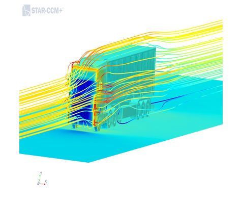
Explore the fundamentals of vehicle dynamics and ultimate trends in the field from design and modeling to control with Skill Lync's exclusive course on the subject. Read about how Skill-Lync's CAE courses can help you get employed.
28 Jul 2020
In this article, we will briefly discuss the working, applications, and features of the one-dimensional systematic simulation tool, GT-Power, in Emission Control Strategy, engine calibration, hybrid vehicle modeling. Read about how Skill-Lync's CAE courses can help you get employed.
28 Jul 2020
This article offers a brief introduction to the globally accepted standard of Geometric Dimensioning and Tolerancing, and its importance for the entire manufacturing process. Read about how Skill-Lync's CAE courses can help you get employed.
28 Jul 2020
In this blog we will read about Going a step into Biomechanics and how Skill-Lync's CAE course will help you get employed.
09 May 2020
The powertrain is the most prominent source of vibrations that affects the driving experience for the people on board. This blog from Skill-Lync examines these vibrations to help enhance that experience.
21 Aug 2020
Author
Skill-Lync
Subscribe to Our Free Newsletter
Continue Reading
Related Blogs
Explore the fundamentals of vehicle dynamics and ultimate trends in the field from design and modeling to control with Skill Lync's exclusive course on the subject. Read about how Skill-Lync's CAE courses can help you get employed.
28 Jul 2020
In this article, we will briefly discuss the working, applications, and features of the one-dimensional systematic simulation tool, GT-Power, in Emission Control Strategy, engine calibration, hybrid vehicle modeling. Read about how Skill-Lync's CAE courses can help you get employed.
28 Jul 2020
This article offers a brief introduction to the globally accepted standard of Geometric Dimensioning and Tolerancing, and its importance for the entire manufacturing process. Read about how Skill-Lync's CAE courses can help you get employed.
28 Jul 2020
In this blog we will read about Going a step into Biomechanics and how Skill-Lync's CAE course will help you get employed.
09 May 2020
The powertrain is the most prominent source of vibrations that affects the driving experience for the people on board. This blog from Skill-Lync examines these vibrations to help enhance that experience.
21 Aug 2020
Related Courses