Wiring harness routing & packaging Rules Week 3 Challenge
Q1. Download following cad data & define it as Electrical support using Electrical Part design Workbench. Define all the necessary properties.
https://drive.google.com/file/d/1cL9NiCnMl1I0SGlRESUZwdjSP5_9eAlb/view?usp=sharing
Note: if you face any issue with point definition, point selection, Right-click on the point definition window and use the reset option.
Answer:
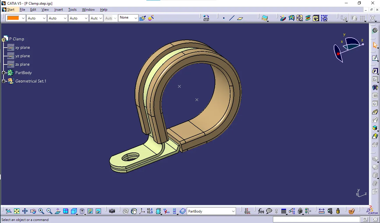
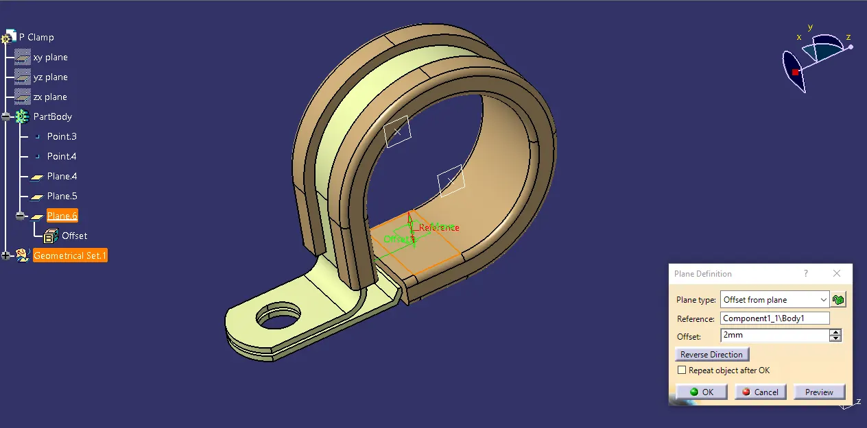
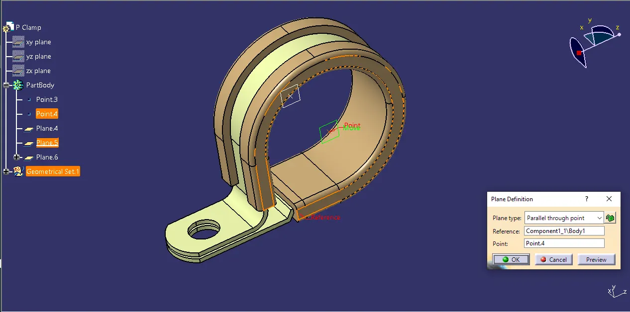
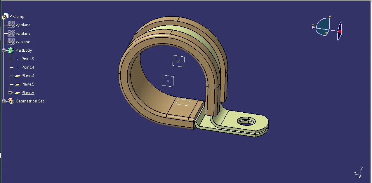
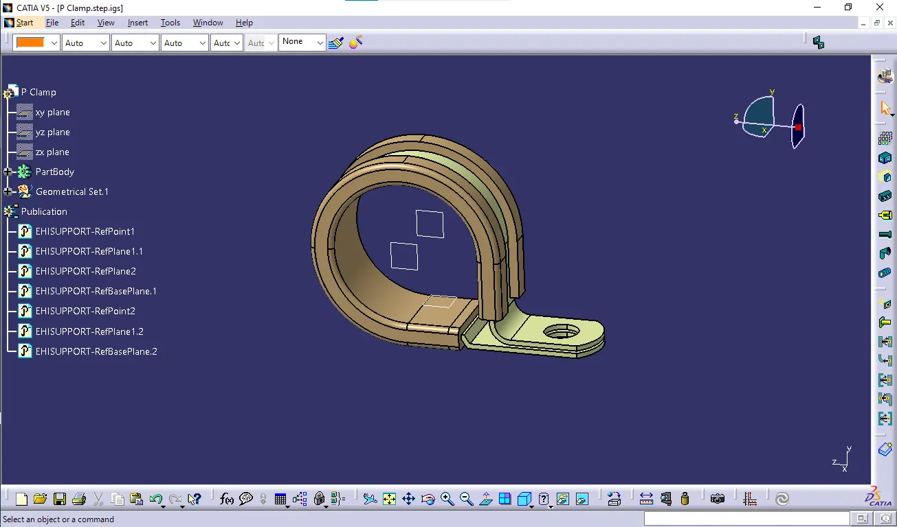
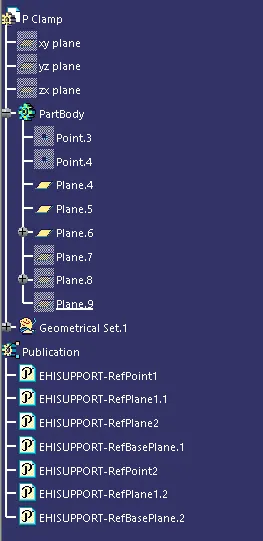
Step by step procedure to define clip/clamps Electrically is shown below;
1) Create two points one as entry and another as exit point.
2) create planes at two points and another at base.
3) Switch to Electric part design
4) Click on support defination - select part - select entry point - select entry plane, exit and base plane.
5) Again Click on support defination - select part - select exit point - select exit plane and base plane as secondary plane is automatically taken or taken as default plane by catia.
Q2. Download following Back shell cad data & define it as Electrical back shell using Electrical Part design Workbench. Define all the necessary properties.
Tyco 1738312-1 https://www.te.com/usa-en/product-1738312-1.html
Answer:
1) create Back shell entry point.
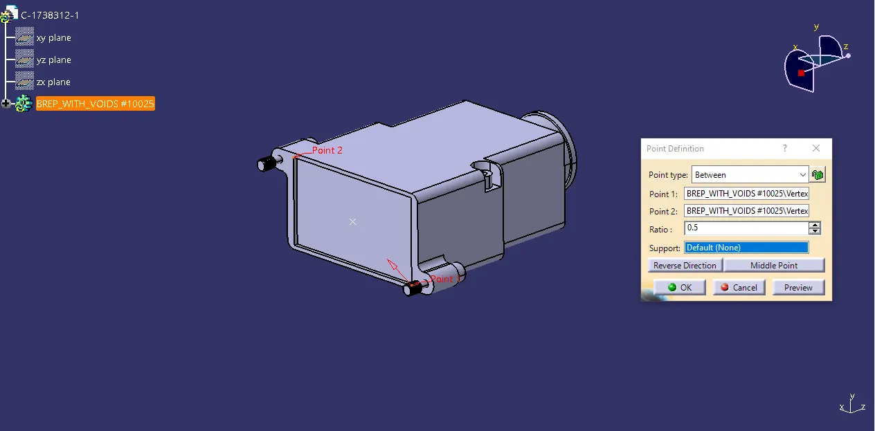
2) create axis system for back shell entry.
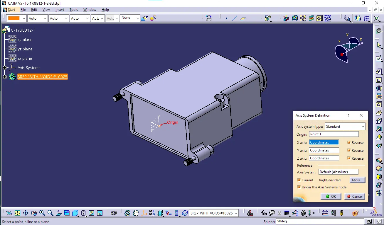
3) create bundle connection point.
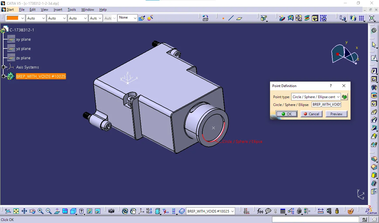
4) switch to Electrical part design.
5) Define part electricaly as back shell.
6) Then define Back shell connection point.
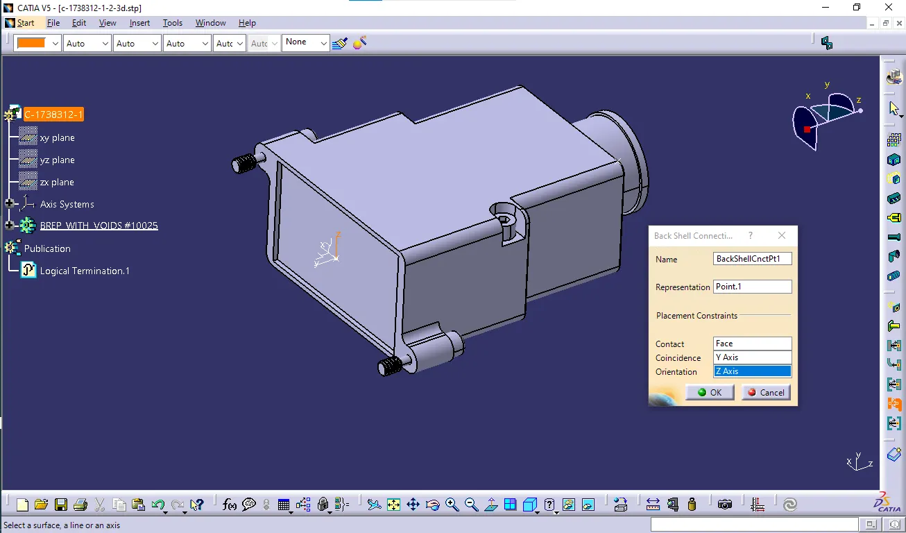
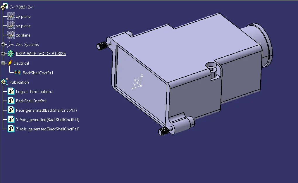
7) Define bundle connection point.
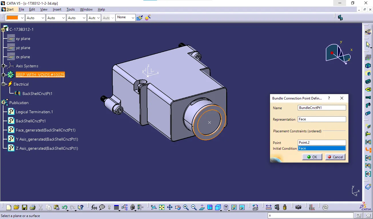
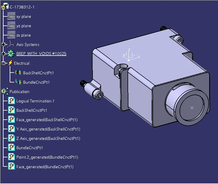
Hence, Backshell is electrically defined.
CATALOGUE CREATION PROCESS:
Aim:
Creating the catalogue document for the connection of similar components. The goal of the catalogue is to create a classification of part documents which contains design of connectors, screws, clips, insulation tubes etc.
Steps to be followed to create a catalogue document:
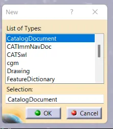
- In the File menu, click New.
- Select Catalogue Document under that. And click OK.
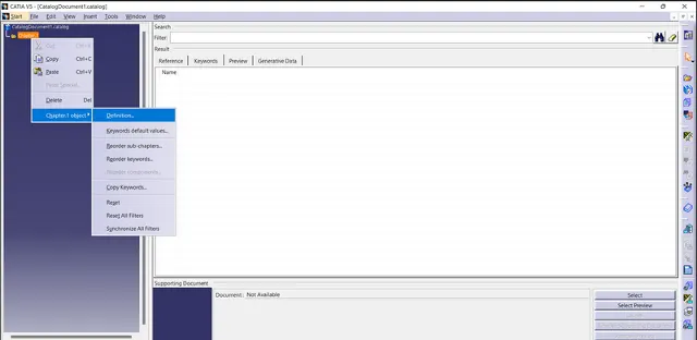
- In the left corner, click on Chapter.1 object and go to Definition.
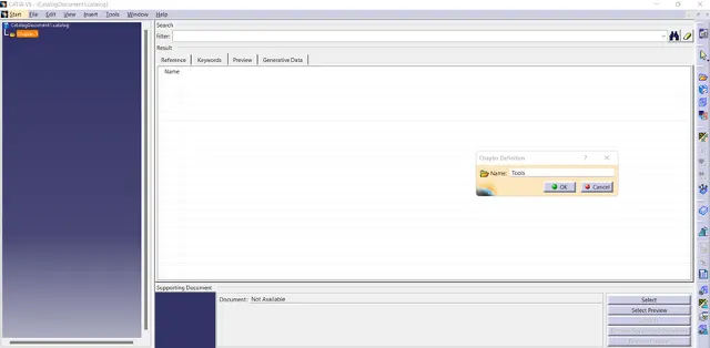
- Under Name tag, type Tools and click OK.
- Click on Add Family
 which is present in the right side of the window and creates a family to store Connectors and select type as Electrical.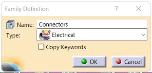
- Click on Add Family again and create a family to store Clips.
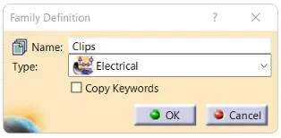
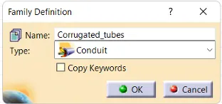
- Create a family to store Corrugated tubes of different sizes.
- We can observe the created family in the catalogue document.
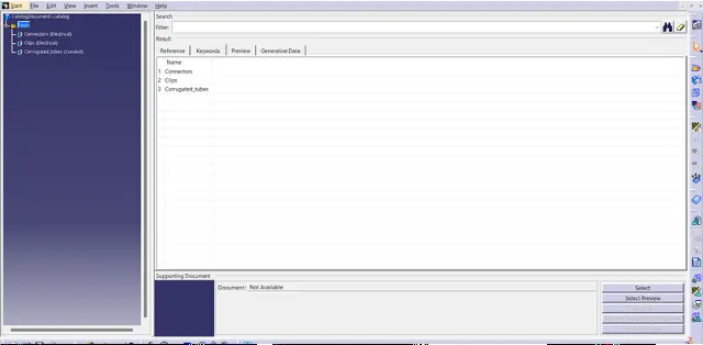
- Save the document using the File ---> Save option.
- After Part definition of each components, under Electrical part design workbench use Store device
 option to store the components in the particular catalogue document and family. Q3. Create Following Corrugated tubes & Add them in Catalogue under “Slit COT” family.
Answer:Name
ID (mm)
OD (mm)
Thickness (mm)
15mm COT
12
15
1.5
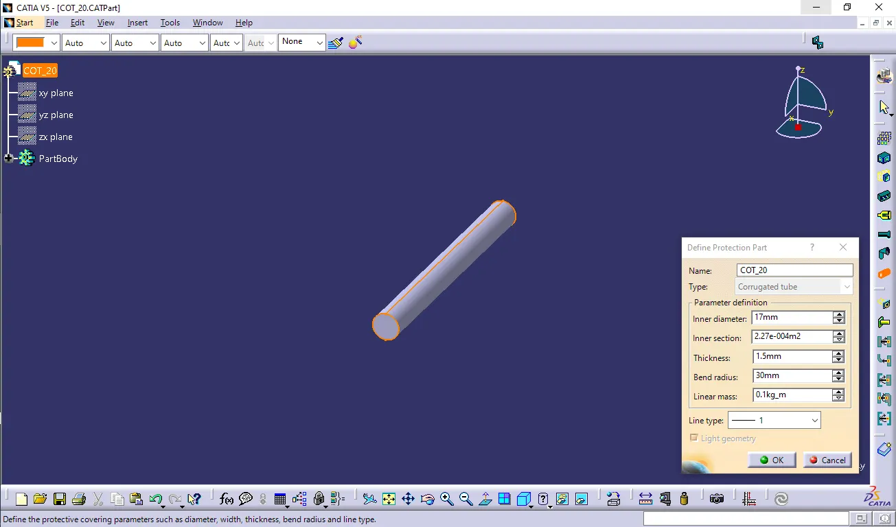
20mm COT
17
20
1.5
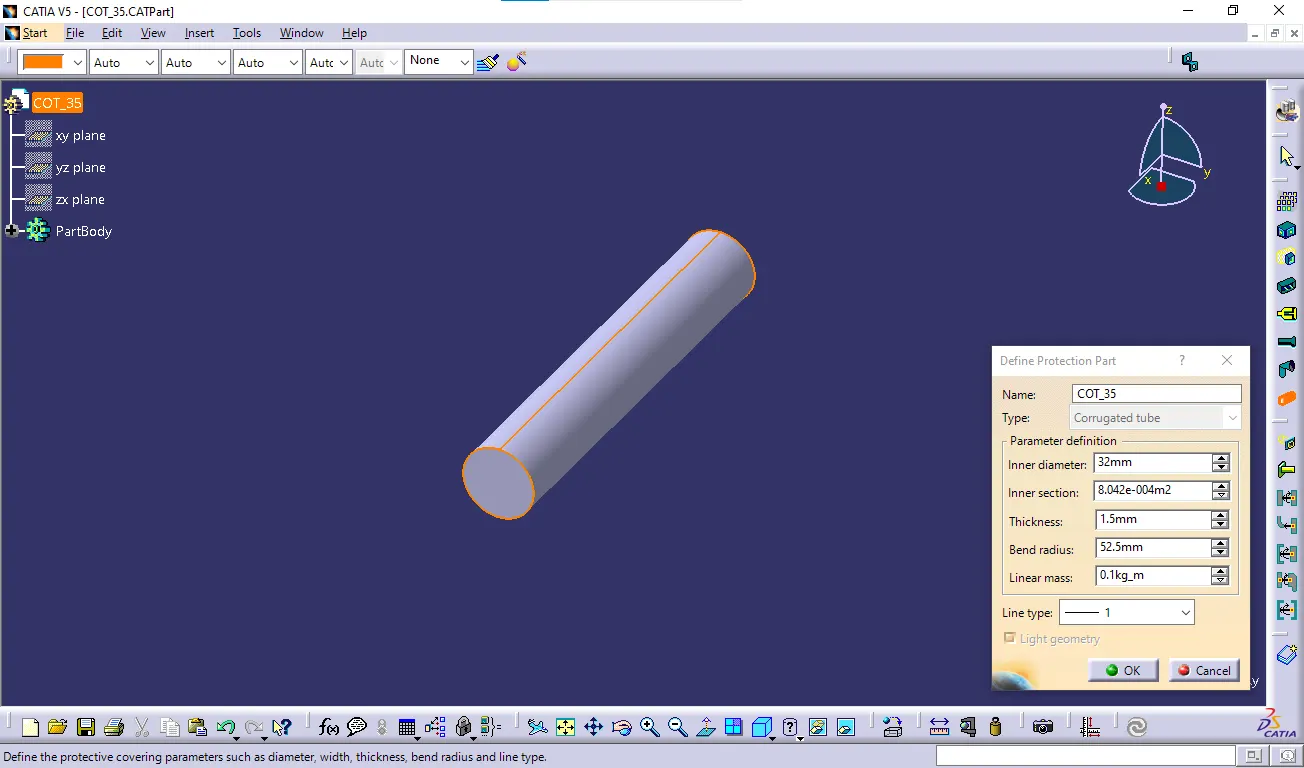
35mm COT
32
35
1.5
10mm COT
7
10
1.5
5mm COT
3
5
1
1) Create new part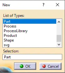 2) Switch to Electrical part design 3) Select Define protection Part 4) Click on part (on file name in specification tree) 5) Provide given parameters and bend radius as '1.5 x Outer Dia'. 15mm COT
 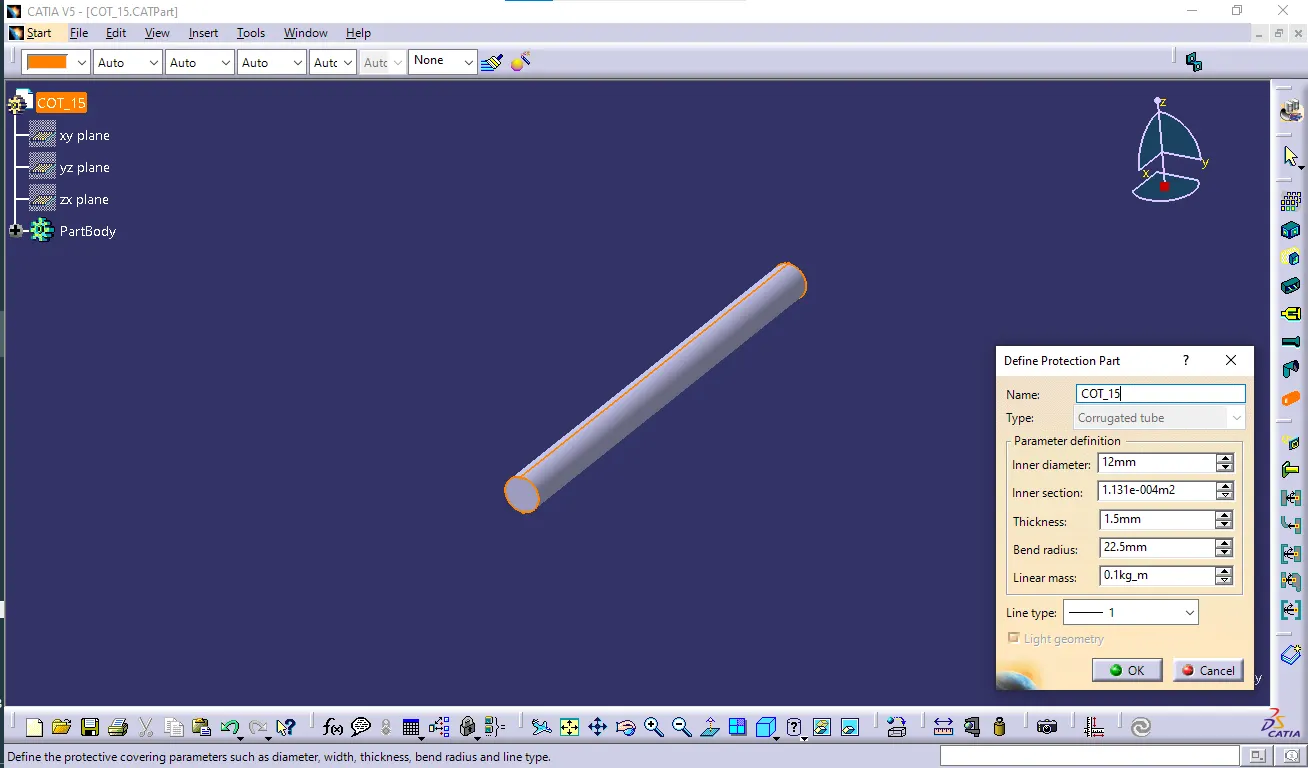 20mm COT
  35mm COT
  10mm COT
 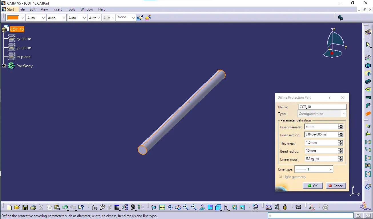 5mm COT
 Catalogue Cretation:
- new part - catalogue document - add family - give name - type - select Conduit - save.
- Open part to add catalogue - store device command - select catalogue - family - Slit_cot_tube - ok