Week 9 - Challenge 3 - Bumper
Inputs:
- Class A Surface of the Bumper (STEP Used).
- Thickness of Plastic Part - 3 mm.
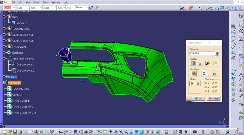
Screenshots of the Draft analysis report for both the given Class-A surface and the final plastic component:
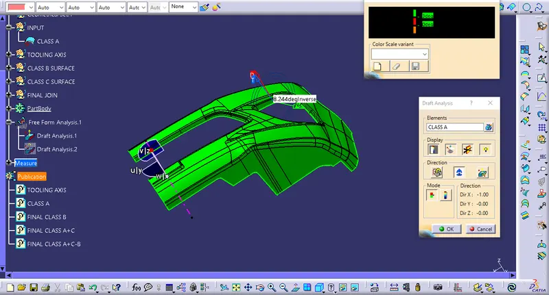
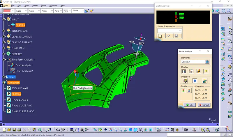
Class A Surface Draft Analysis Report:
- In is given class A surface dont have any below 3 Dgree draft or any other negative value.
Here below 3 various face angle verfied images as below by draft angle analysis method,
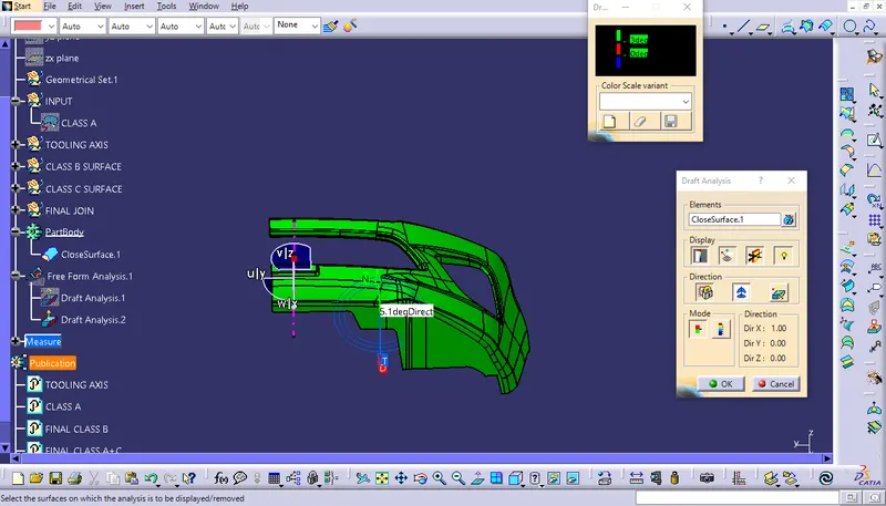
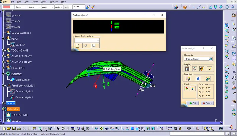
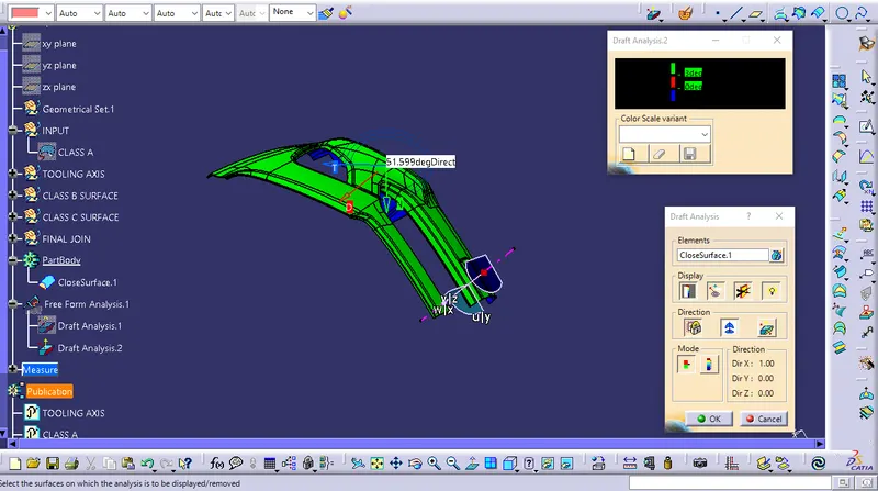
Final Product Closed Surface Draft Analysis Report:
Here below 3 various face angle verfied images as below by draft angle analysis method,
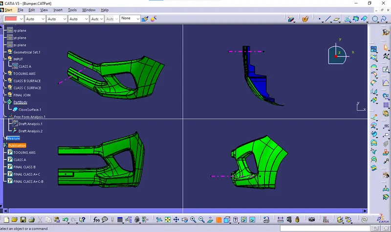
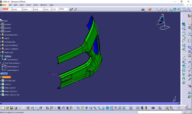
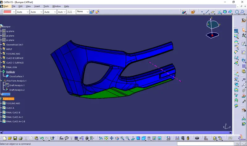
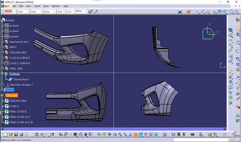
Screenshots of the solid model with the proper color code of the draft angle in various orientations and various views:
Detailed Report of the Bumper:
I have start work with inputs of Class A surface which received(STEP Used).
Tooling Axis Creation:
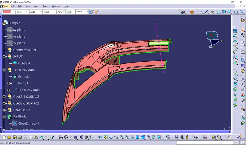
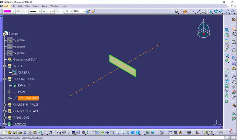
- In this Class A surface have flat face extract and point created.
- Normal line created with select point and perpendicular line created for the surface.
- This line consider as tooling axis.
- later I have done draft analysis for the class A surface also verified the created tooling axis.
Below Image for the Tooling Axis create Screen shot,
Class B and Class C Surface Create:
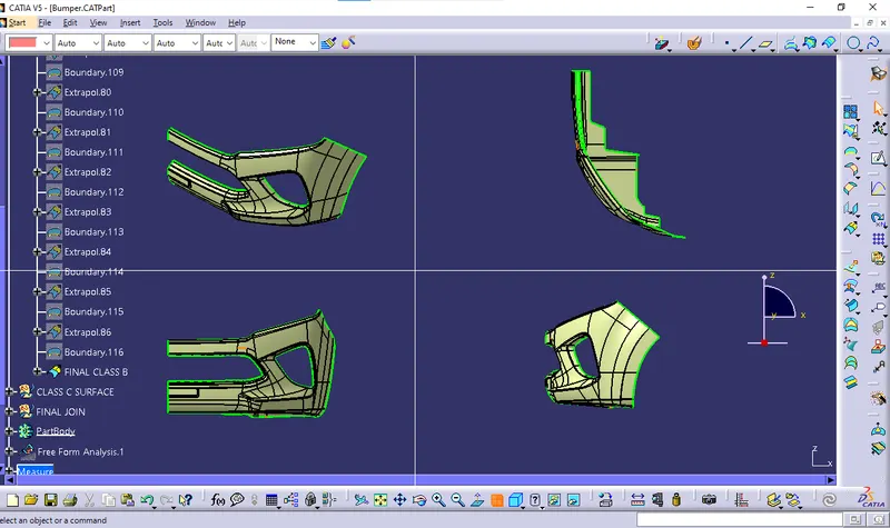
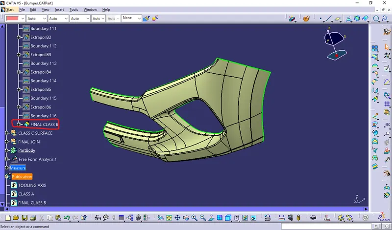
- In order to creating the B surface, i just offset the Class A but i get some error of gap then i just accept with the offset surface.
- first remove unwanter surface with help of tool multiextract then boundary extracted then extrapolate on both and i just did trim to created the B Surface.
- the measure fillet size on all the radius portion and i provided fillet on created B surface at required portions.
- then finally i go B surface.
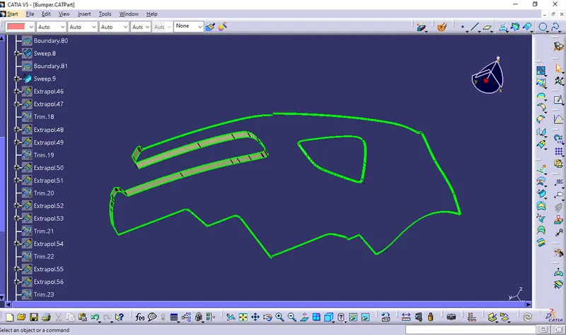
- To craete C surface, I had followed 2 type of sweep first one is draft angular sweep second one is sweep with reference surface.
- accourding to the b surface needs i sweet the extracted boundary on 5 batches then i just extrapolate at required portion of the created surface for C then trimed as required.
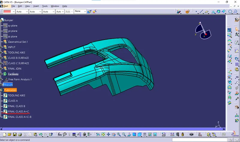
- Then finally i got join the Class A with C surface to create A+C.
B Surface Image:
C Surface Image:
C+A Surface Image:
Final Trim:
Once all to gethered - B & C Surfaces.
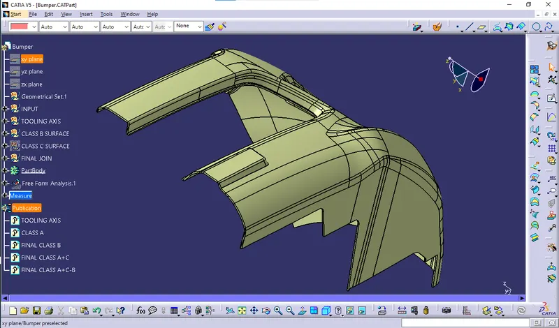
Have join the C surface with Class A and got join as per above picture.
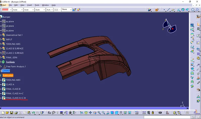
Then later B Surface trim with Join to make closed surface.
Final Trimed image as below,
Solid Body:
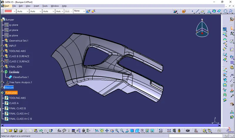
Final solid created by inputs of the above final trim Bumper Designed surface.
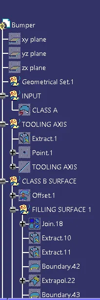
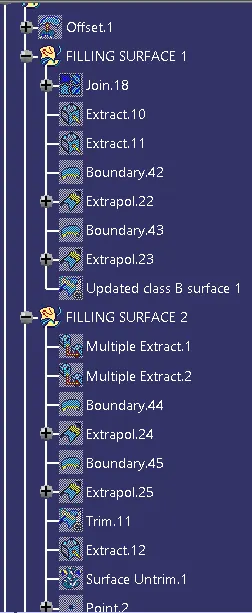
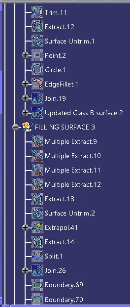
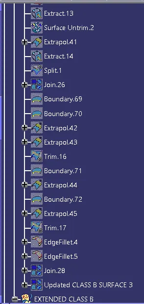
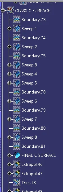
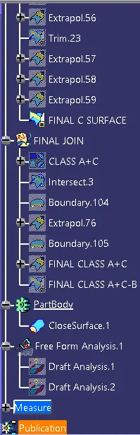
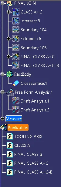
TREE STRUCTURE: