Week 9 - Challenge 1 - Base Bracket Design
Week 8 - Challenge 1 - Base Bracket Design
Inputs:
- Class A Surface of the Base Bracket.
- Thickness of Plastic Part - 2.5 mm.
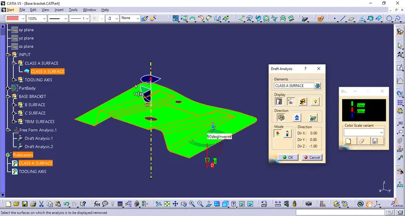
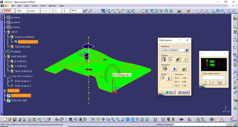
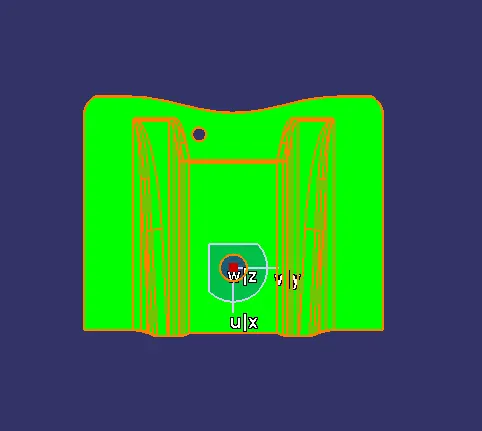
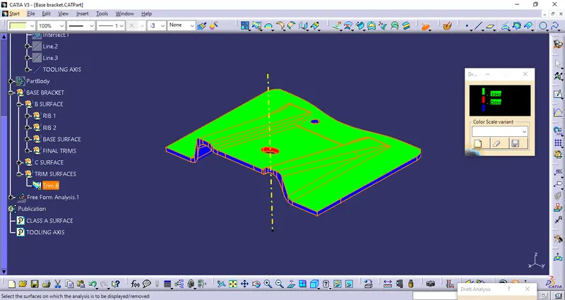
Screenshots of the Draft analysis report for both the given Class-A surface and the final plastic component:
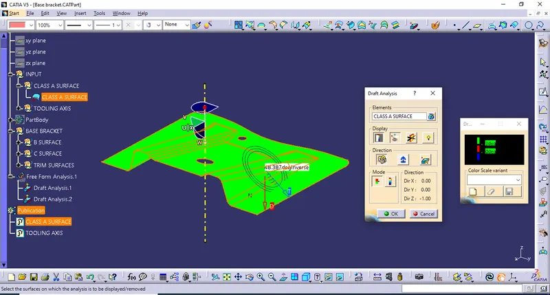
Class A Surface Draft Analysis Report:
Here below 3 various face angle verfied images as below by draft angle analysis method,
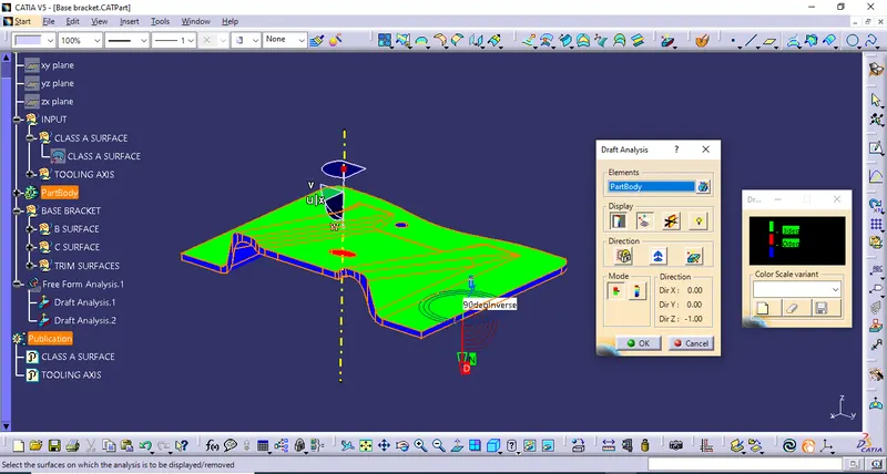
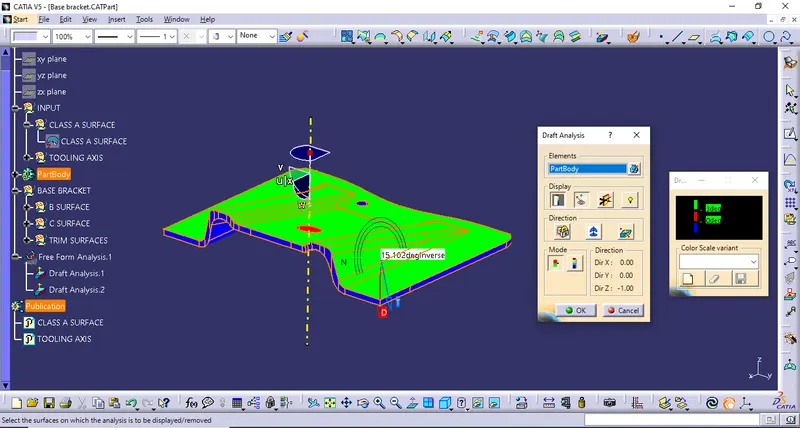
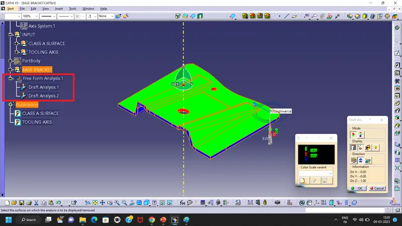
Final Product Closed Surface Draft Analysis Report:
Here below 3 various face angle verfied images as below by draft angle analysis method,
Images of the color scale variant:
- Green color is indicating upto 3`dgree`
- Red color is indicating upto 0`dgree`
- Blue color is indicating upto Below 0`dgree` or Negative Value.
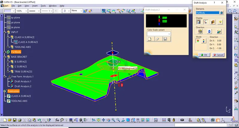
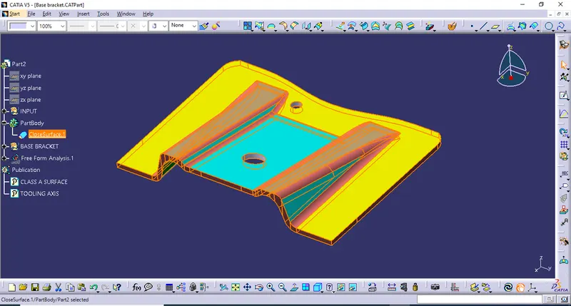
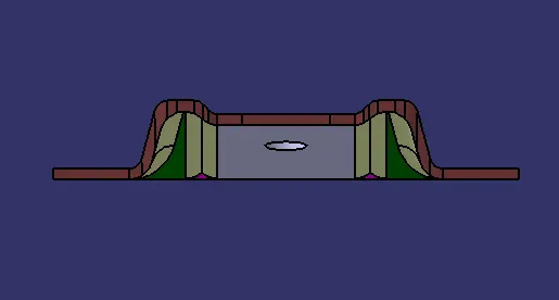
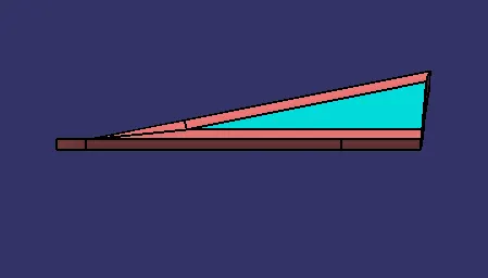
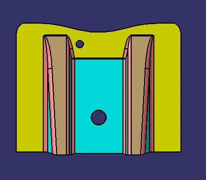
Screenshots of the solid model with the proper color code of the draft angle in various orientations and various views:
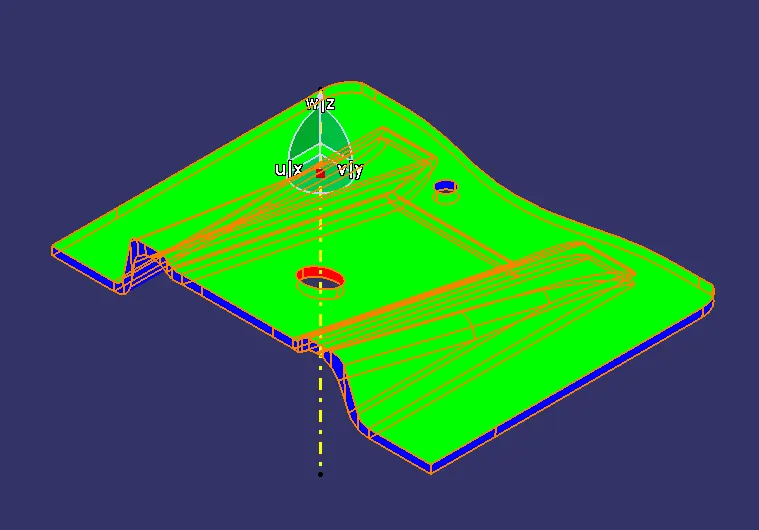
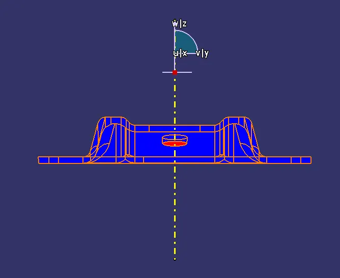
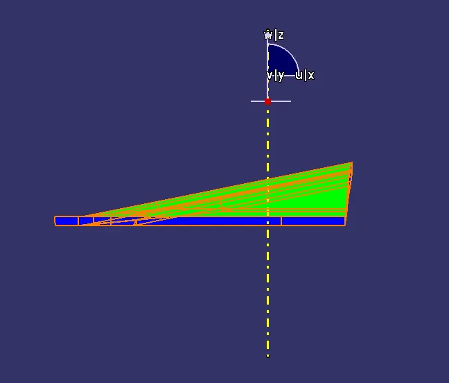
Detailed Report of the Base Bracket Design:
I have start work with inputs of Class A surface which received.
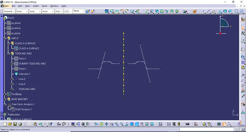
Tooling Axis Creation:
- Firstly with after suitablity research of tooling axis then decide to created boundary with help of class A surface holes for Center point creation for tooling axis.
- Secondly Class A surface supporting line create to make tooling axis in a Bisecting line creation method.
- Finally Tooling Axis created by the way of bisecting method line creation.
Below pic of yellow line is considering as Tooling Axis of the Base Bracket.
Class B and Class C Surface Create:
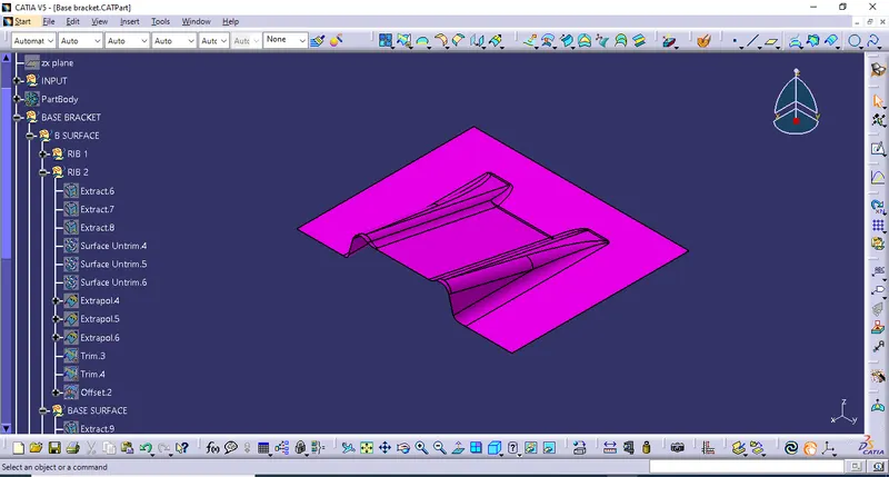
- To create B Surface, using Extract tool on draft surface then extracted surface to be untrim then extrapolate.
- Extrapolated surfaces are Trim with respected needs of profiles.
- All the process done with considerarion of base bracket input thickness of 2.5mm.
- Then Rib-1 & Rib-2 Created by interset and trim methods
- Then Base face project with use extract tool with inputs of class A surface.
- Final R value provided as per considering to manage the thickness.
- Final Trim done on the Ribs, Base 1 and Main Base the final out come of trim is considering as B surface.
Below picture is B Surface of Base Bracket,
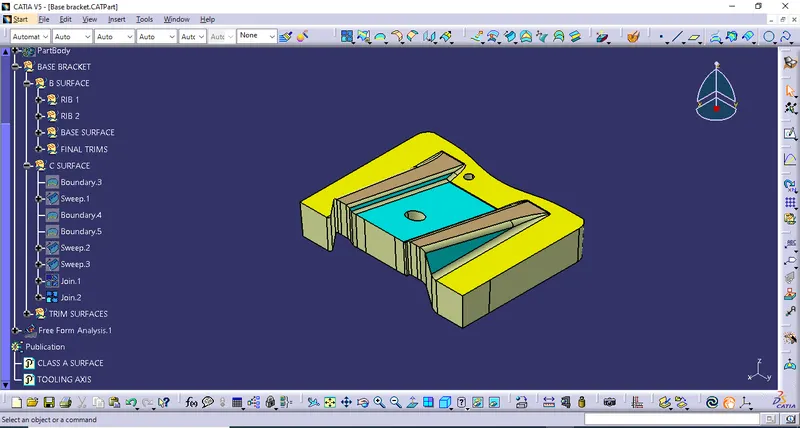
- To create C Surface, have created boundary of Class A surface then sweep with providing draft direction and draft angle 3 Dgree.
- Then once sweep the surface accouring to the draft angle with guideness of tooling axis then Holes are projected and holes separate sweep surface created.
- Then finally join all of the sweeps and created single join then final join done with class A surface extract surface as consideration of C Surface.
Below picture is C Surface of Base Bracket,
Final Trim:
- Once createing the B & C surface, trim each to other as respected needs with considered to make final outcome of closed surface.
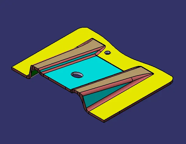
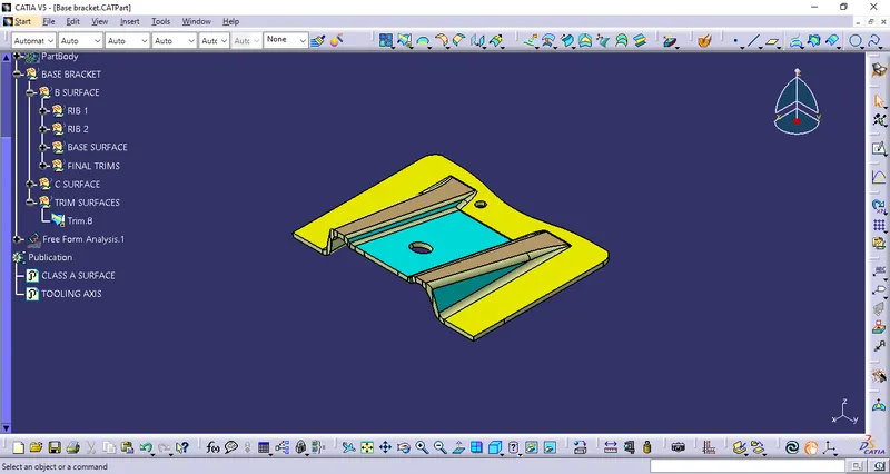
- The final trim surface is considering As closed surface of final product as a Base Bracket.
Below picture is final closed surface of base bracket,
Solid Body:
Final solid created by inputs of the above final trim base bracket surface.
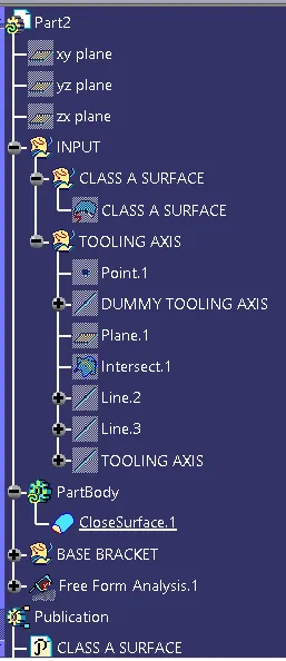
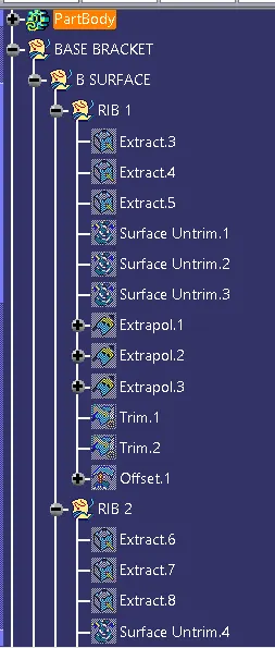
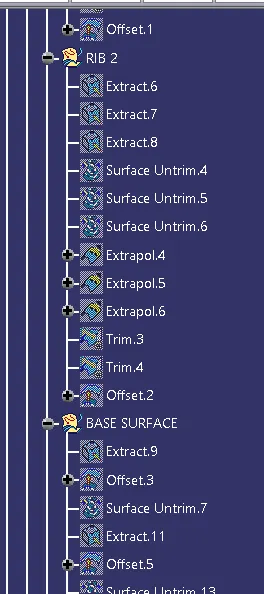
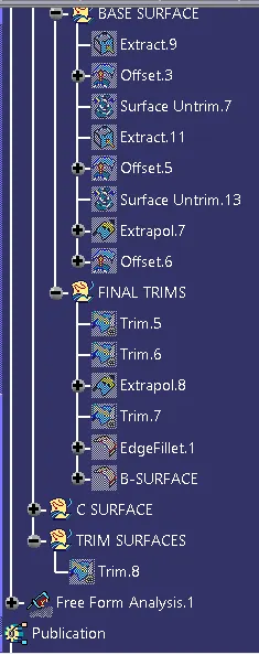
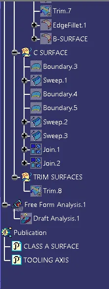
TREE STRUCTURE: