Wiring harness routing & packaging Rules Week 3 Challenge
P clamp
First downloaded file from given link open mechanical part design.
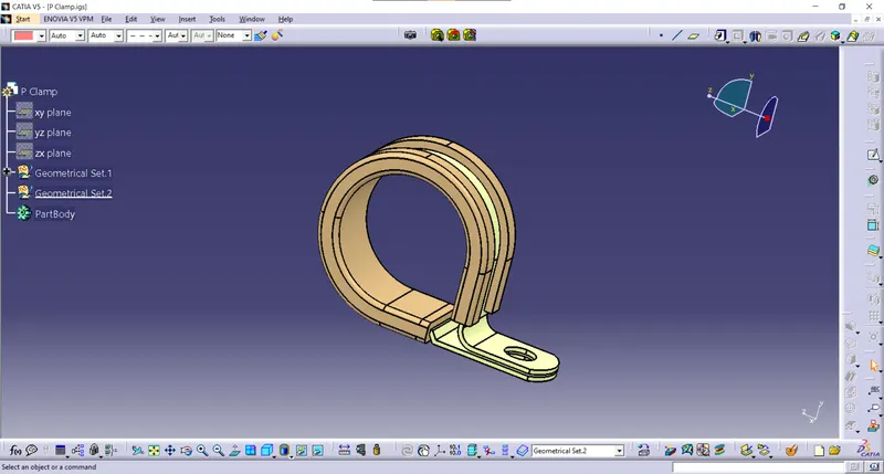
Insert the point using the circle center option
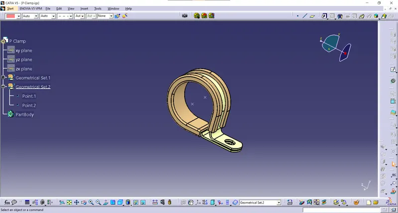
Insert the plane on entry exit side using the plane type parallel through point option on the already existing point
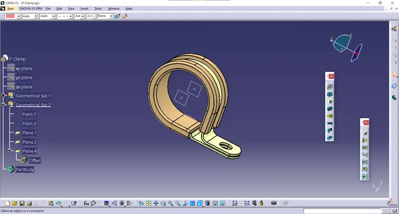
Created plane for base by offering 2mm from the base surface.
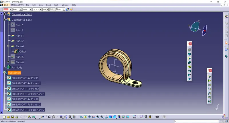
Then open the Electrical part design defined as support on the Wire Entry side.
Defined as support on the wire exit side. completed the support definition.
CONNECTORS
Tyco 1738312-1
Back shell
Download the file from the given link opened in mechanical part design.
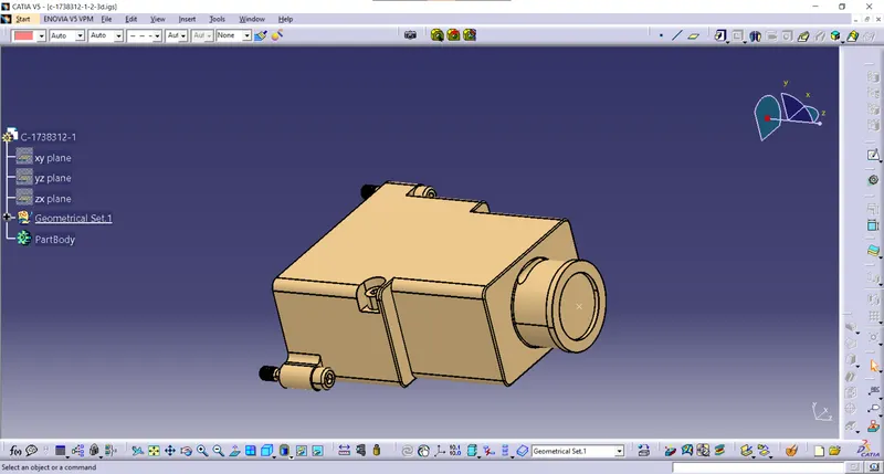
The back shell connects the side defined point by between point
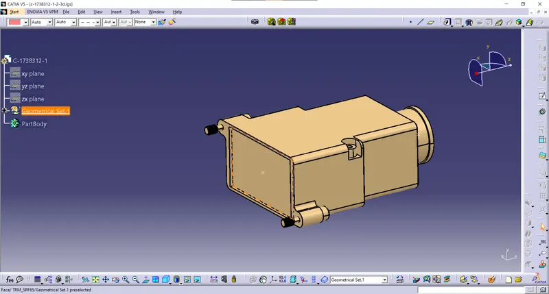
Insert axis system on the side on the create points
In the axis system x-axis is rotated 90 degrees to make Y-axis coincide side.
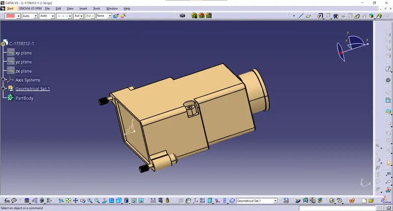
change it from part design to electrical workbench and define it as back shell and
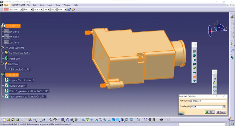
The defined point on the Bundle connection side.
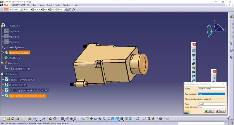
Then Defined Back shell connection point.
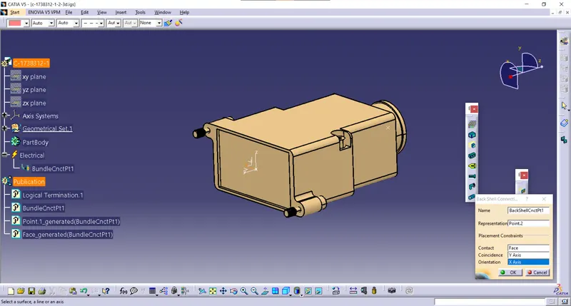
Corrugated tubes
15mm COT
First opened a new part file in the electrical part design.
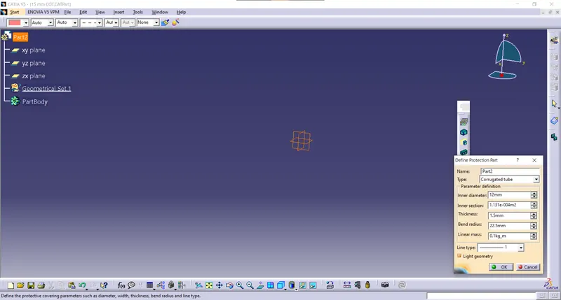
then click on the define protection part and and enter the parameters required
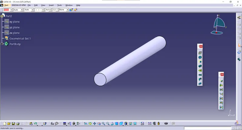
Add the cot tube to catalogue By store device option
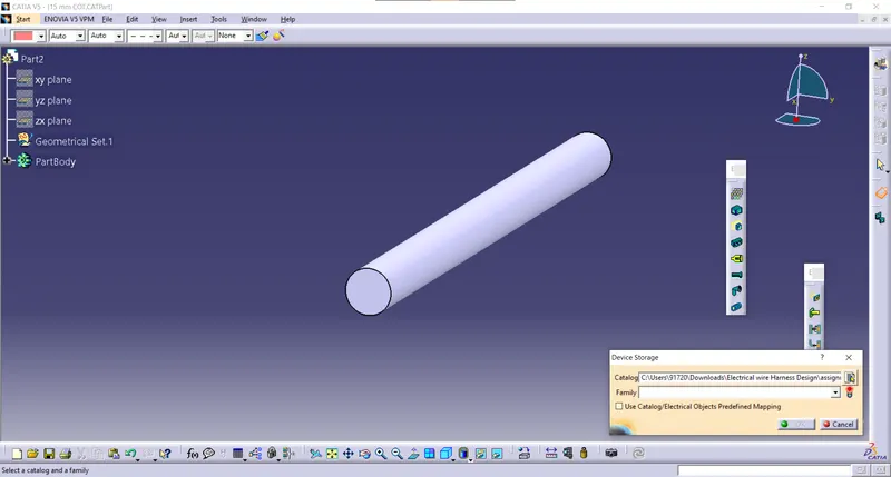
20mm COT
First opened a new part file in the electrical part design.
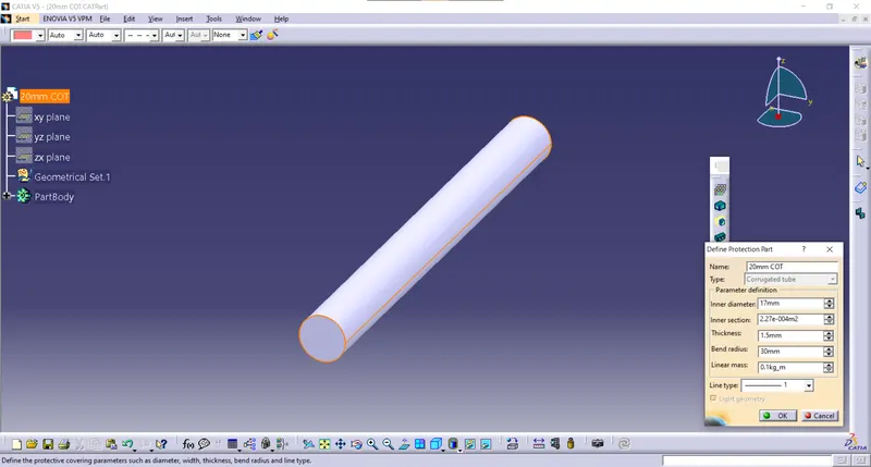
then click on the define protection part and and enter the parameters required
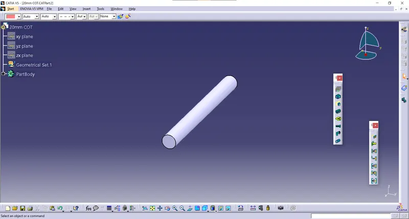
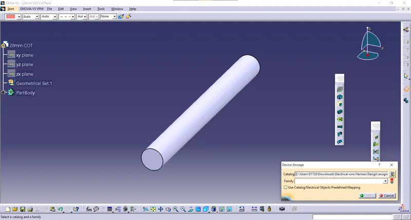
Add the cot tube to catalogue By store device option
35mm COT
First opened a new part file in the electrical part design.
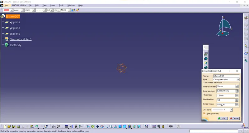
then click on the define protection part and and enter the parameters required
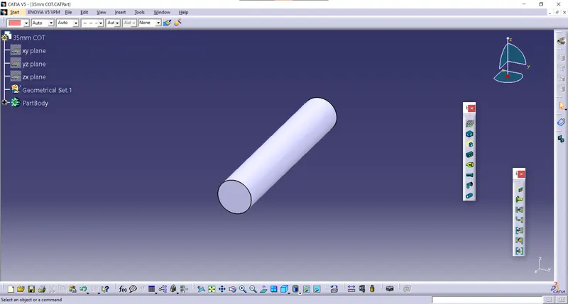
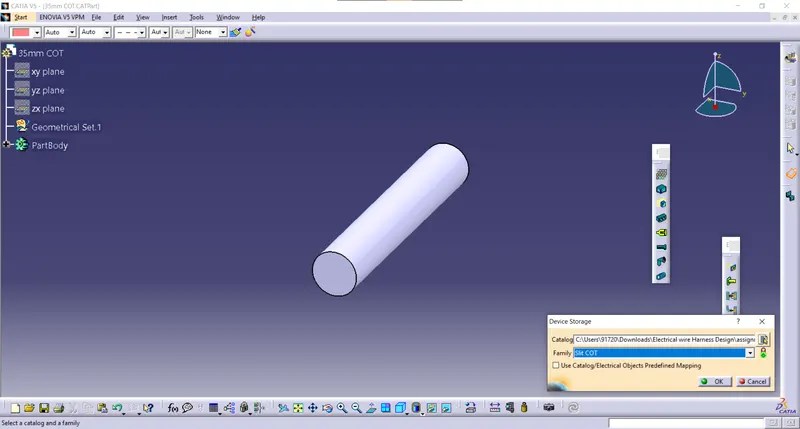
Add the cot tube to catalogue By store device option
10mm COT
First opened a new part file in the electrical part design.
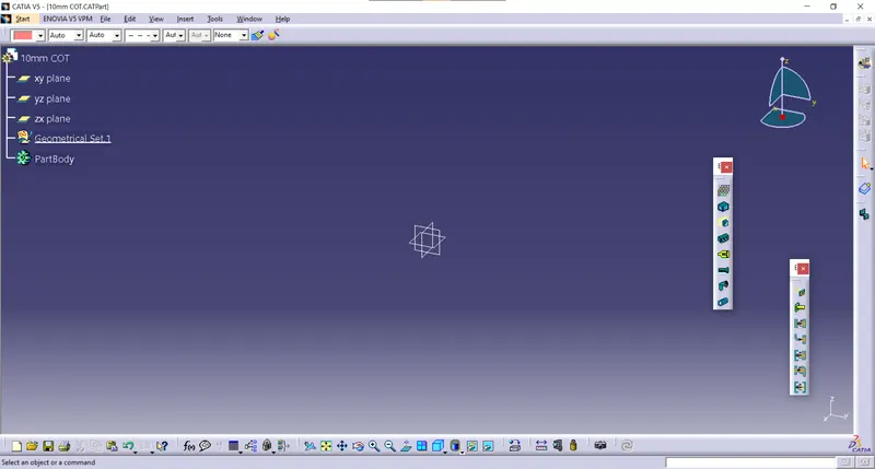
then click on the define protection part and and enter the parameters required
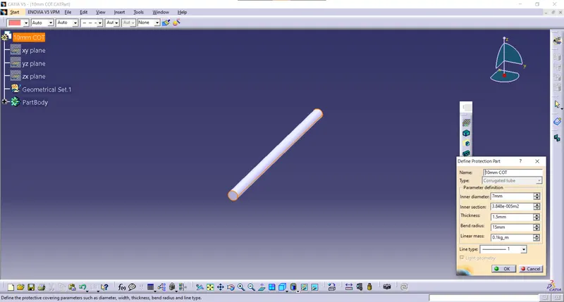
Add the cot tube to catalogue By store device option
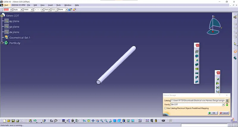
5mm COT
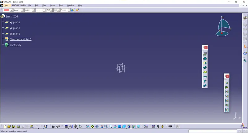
First opened a new part file in the electrical part design.
then click on the define protection part and and enter the parameters required
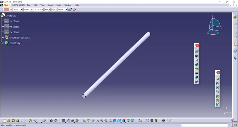
Add the cot tube to catalogue By store device option
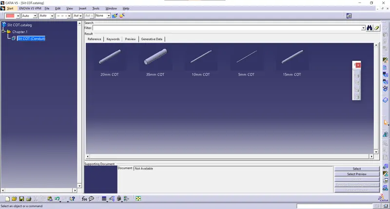
catalogue