Wiring harness routing & packaging Rules Week 3 Challenge
- P Clamp : It is a component used for the hold the wire bundddle at desired position as it will be fitted to desired places using nut and bolts.
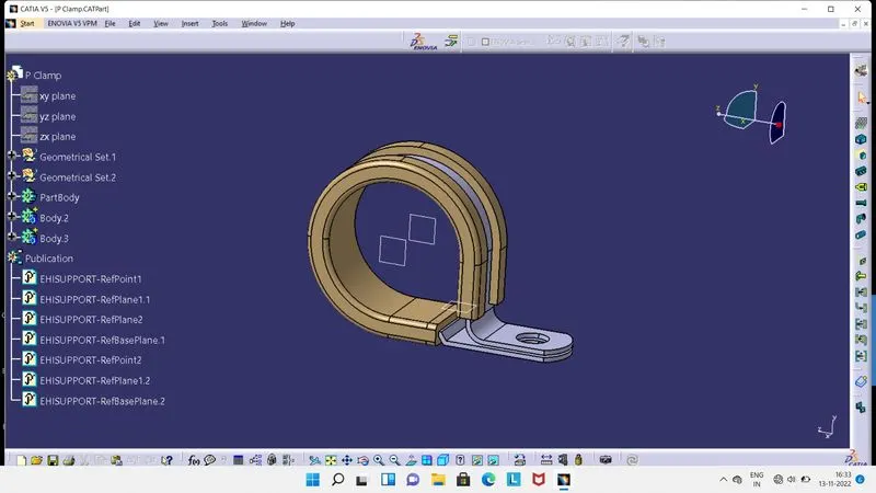
- To define the above shown P Clamp in Electrical Workbench, we have to required Points and Planes at required places, which we have to create in Part Workbench.
- As we have Points and Planes, we can shift to Electrical Part Workbench.
- Here we have to click on ' Define a Support ' tool and then on P Clamp, so one box will get appear. In that box we have fill required data.
- In this box, its ask for 1st Point and Plane, 2nd Plane and Base Plane.
- So we can see in above image, we have created Three Planes and Two Points. Vertical two Planes are for Entry and Exit of a wire bunddle and Horizontal Plane for Base.
- According to it, we have to select Points and planes in that box. As there is two possible ways for Entry and Exit of Wire Bunddle in P Clamp, so we have to 'define the support' 2nd time with 2nd Point and Plane as a 1st Point and Plane. If we face difficulty in click on Point, then we have to right click on that section, so we can see a Reset option there. We have click on it, so now we can able to click on Point.
- Hence, P Clamp is now defined in Electrical Part Workbench, in Publication we can see all data.
- Backshell : It is component used to protect the connection area of Wire Bunddle with Connector. It connected at the Bunddle Entry side of the Connector and its as not compulsory to use, depend upon cost and budget criteria it can be used.
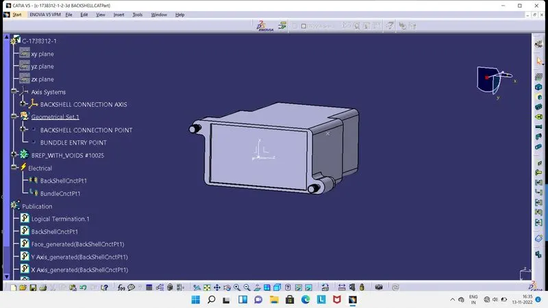
- To define Backshell as a Electrical Part, we have to required Points and Axis, which we have to create in Part Workbench.
- As Points and Axis we have, we can shift to Electrical Part Workbench.
- Here we have first click on 'Define Backshell' tool then on component, so component will get define.
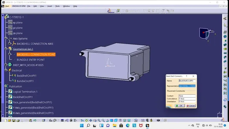
- Then we have define Backshell Connection Point, so now click on 'define backshell connection point' tool.
- So one box will get appear on screen as shown in above image, in this box we have to fill the required data.
- In Name section we can give as per our need, in Representation, we have to select a Backshell Connection Point, which we had created in Part Workbench.
- Then in Contact, select a face which will make contact with connector, in Coincidence, select Y Axis and in Orientation, select X Axis.
- So we can see this data in Publication and in Electrical at Tree Structure.
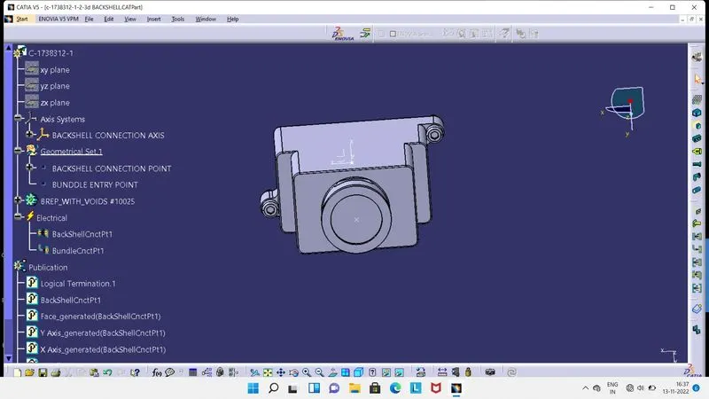
- Now we have to define Bunddle Connection Point, For that we to click on 'define bunddle connection point' tool.
- From here entry of Bunddle will take place.
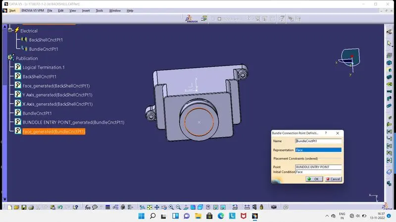
- As we click on 'define bunddle connection point' tool, a box will get appear on screen as shown in above image.
- Here we have to fill required data. In name section we can give as per our need.
- In Representation, we have to select a face which is normal to the Bunddle, in Point we have to select Point which had created for Bunddle Entry Point.
- Then in Initial COndition, select a face which is normal to the Bunddle.
- Hence, Backshell is now defined as Electrical Part, we can see from Tree Structure all the data in Publication and Electrical.
- Corrugated Tube : Its a Protective Covering, used to cover the wire bunddle to protect the bunddle from external environmental effects and give esthetic appearance.
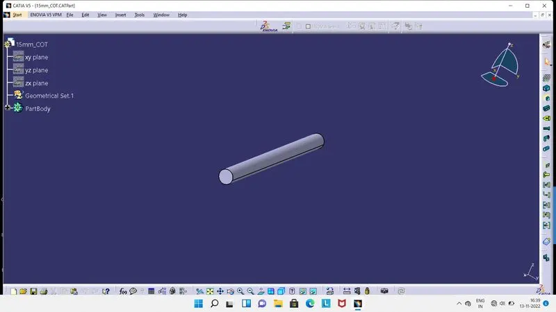
- Its look like a pipe or tube structure as seen in above image, its a 15mm Corrugated Tube.
- We have to create this Corrugated tube inside the Electrical Part Workbench, for that we required internal and external diameter and thickness for it.
- So, as having data for external, internal diameter and thickness, we can procced. So now click on 'Define Protection Part' tool then click on Part Body.
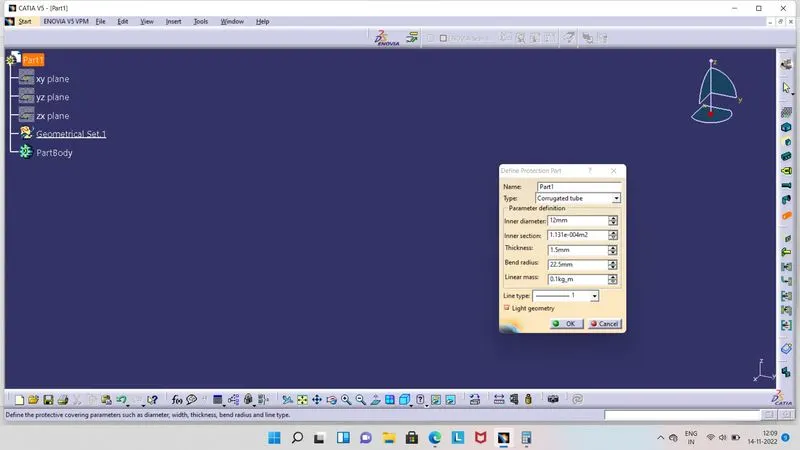
- So one box will get appear on screen as shown in above image, here we have to fill the required data in particular section.
- In Name, we can give as per our need. In type, we have to select Corrugated tube.
- Inner diameter is 12mm, Thickness is 1.5mm and Bend radius is equal to 1.5 × External diameter, which is 22.5mm.
- As we click on Ok, we will get tube like structure. We can create similarly many Corrugated tubes by simply changing the data as per requirement.
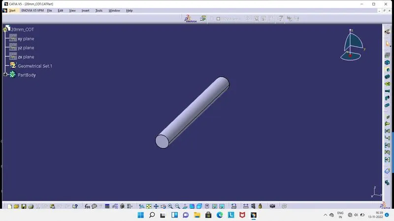
- Its a 20mm Corrugated tube.
- Internal diameter is 17mm, External diameter is 20mm, thickness is 1.5mm.
- Bend radius is equal to 1.5 × External diameter, which is 30mm.
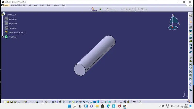
- Its a 35mm Corrugated tube.
- Internal diameter is 32mm, External diameter is 35mm, thickness is 1.5mm.
- Bend radius is equal to 1.5 × External diameter, which is 52.5mm.
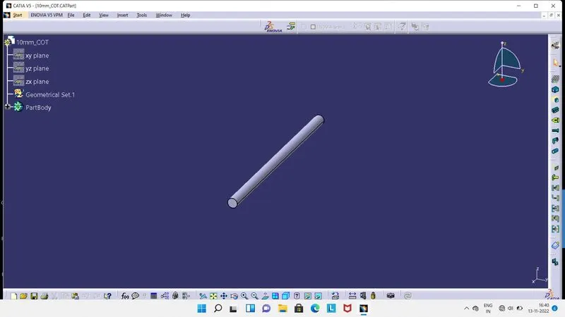
- Its a 10mm Corrugated tube.
- Internal diameter is 7mm, External diameter is 10mm, thickness is 1.5mm.
- Bend radius is equal to 1.5 × External diameter, which is 15mm.
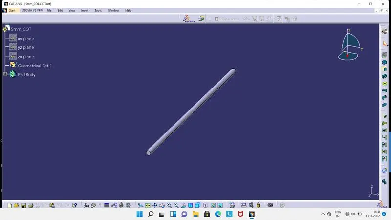
- Its a 5mm Corrugated tube.
- Internal diameter is 3mm, External diameter is 5mm, thickness is 1mm.
- Bend radius is equal to 1.5 × External diameter, which is 7.5mm.