Week 8 - Challenge 1 - Base Bracket Design
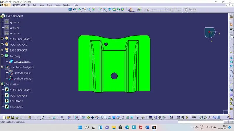
- Screenshots of the Draft analysis report for the given Class-A surface.
- Image of the complete Draft analysis and Images of the color scale variant.
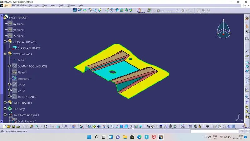
- For Draft Analysis, we need tooling axis.
- Tooling axis is direction line in which core and cavity opens.
- So we have to first decide proper direction in which ease to create our mould, here we have selected Z direction.
- At the center of big hole we have placed a point.
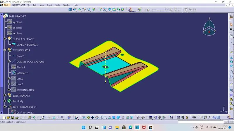
- From that point, we have to create a verticle line in Z direction, which is our Dummy line.
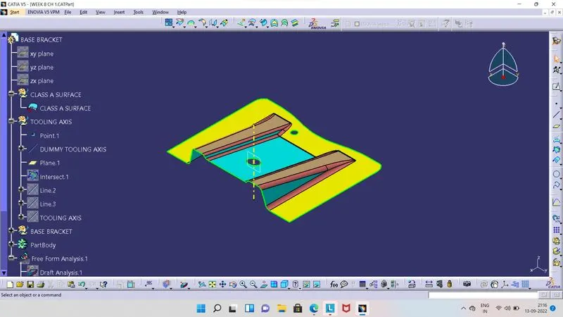
- As we need a bisecting line, so for that we required a profilein that direction. For that, we have selected YZ Plane here, through parallel point. So by using Intersecting Tool at YZ Plane and Class A Surface, we will get Profile according to that. So we will use this profile to create bisecting line.
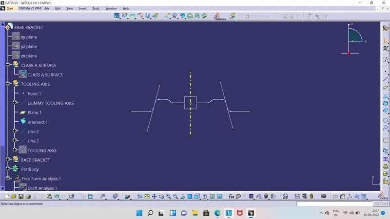
- As shown in image, we have to make a lines by using Point to Point type line at region of profile which is some what parallel to Dummy tooling axis.
- After creating lines at both side of profile, we have to use Bisecting line type and use this two lines and center point, so we will get Bisecting Line, which is our main Tooling axis.

- As we get Tooling Axis, we can go for Draft Analysis.
- For Draft Analysis, insure that our component is in the material view mode, then click on Feature Draft Analysis from Insert > Analysis > Feature Draft Analysis or we can click on it from direct tool bar also.
- As we open the Draft Analysis tool it will get added in Tree Structure as Draft Analysis.1. There are several options in Draft Analysis tool, from there we have to first select on compass. So we can see that compass in screen.
- Placed this compass at Tooling axis in such way that compass should be align with Tooling axis. Then click on lock symbol and then click on Class A Surface.
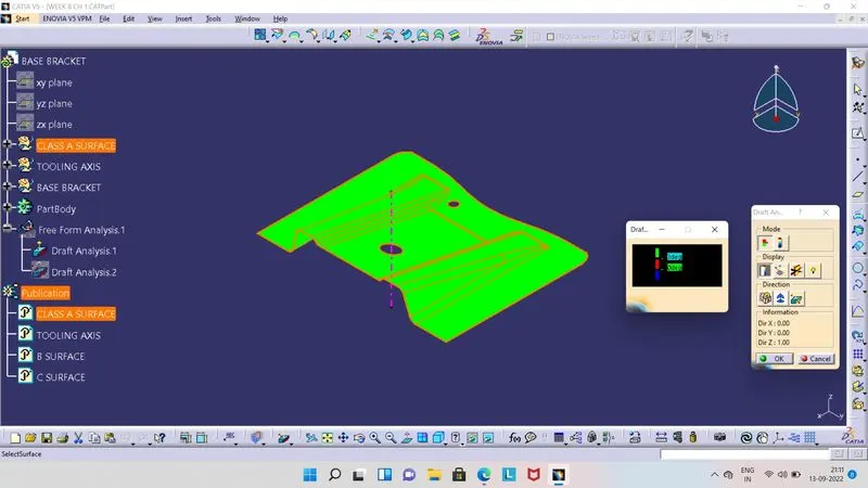
- As we click on Class A Surface, Surface colour get change into Green colour, as shown in above image.
- There is another color coding tool box in the screen besides of Draft Analysis tool, which indicates the Draft Angles.
- Green Colour indicates that, draft angle is above 3 degrees.
- Red Colour indicates that, draft angle is between 0 to 3 degrees.
- Blue Colour indicates that, draft angle is less than 0 degrees or in negative.
- Screenshots of the Draft analysis report for the final plastic component.
- Image of the complete Draft analysis and Images of the color scale variant.
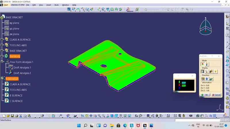
- From above image we can see that Draft Analysis for final plastic component.
- For Draft Analysis of this final plastic component, we have to keep component into the material view mode and select the Draft Analysis tool.
- As we open the Draft Analysis tool it will get added in Tree Structure as Draft Analysis.2. There are several options in Draft Analysis tool, from there we have to first select on compass. So we can see that compass in screen.
- Placed this compass at Tooling axis in such way that compass should be align with Tooling axis. Then click on lock symbol and then click on final plastic product.
- Here we can see above surface of component is in green colour and below surface in blue colour.
- This colour indicates the draft angles.
- Green colour indicates, that draft angle is above the 3 degrees.
- Blue colour indicates, that draft angle is below the 3 degrees.
- Screenshots of the solid model with the proper color code of the draft angle in various orientations.
- Isometric View :
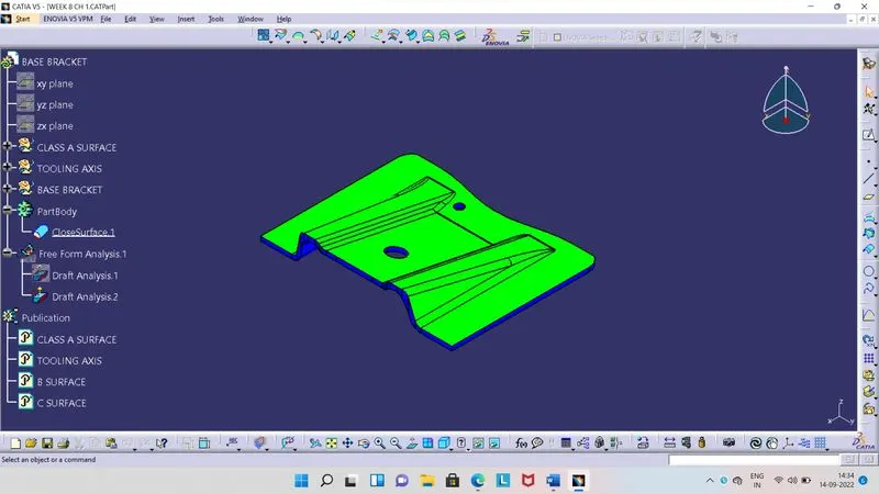
- Front View :
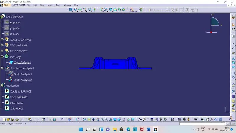
- Side View :
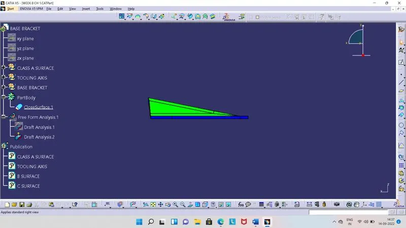
- Top View :