Week 8 - Challenge 6 - Core & Cavity Design
- Screenshots of the Draft analysis report for Switch Bezel surface.
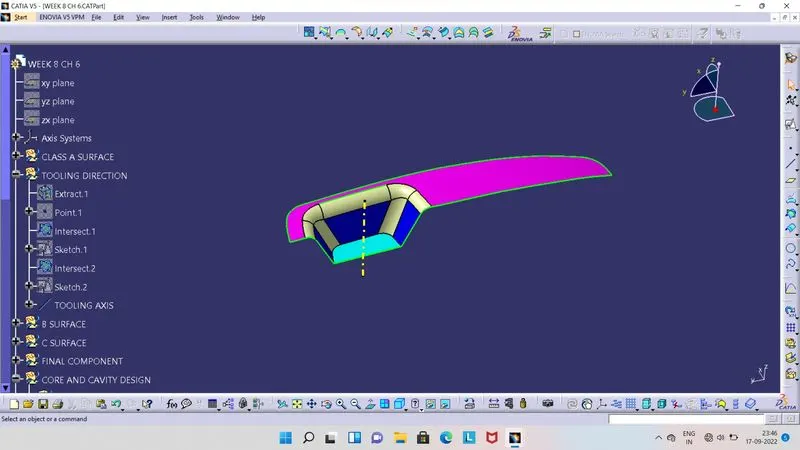
- For Draft Analysis, Tooling Axis is required. So for this component, we exract the base surface and create center point on that and select Axis System.
- Here we can intersect the component with ZY and ZX axis, so from intersection line by projection on it, we can make lines where the line region is parallel to the dummy axis.
- So by using Bisecting line we will get one line from ZY axis and another line from ZX axis, then using this two lines we will get main Tooling Axis by using bisecting line type.
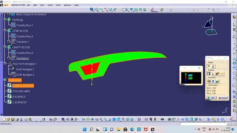
- Once we get the Tooling Axis, we can do Draft Analysis.
- Before doing Draft Analysis, ensure that our component is in the material view mode.
- Then select Feature Draft Analysis tool, so as shown in above image at the right side screen,2 boxes will appear and in the tree structure, Draft Analysis.1 like added.
- So, now we have to click on compass, so compass will be seen to us on screen. Align this compass with Tooling Axis, then click on lock symbol and then click on Class A Surface.
- Surface get colour on it.
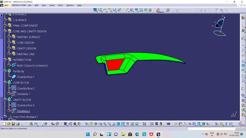
- Green colour indicates the draft angle is above 3 degrees.
- Red colour indicates the draft angle is between 0 to 3 degrees.
- blue colour indicates the draft angle is below the 0 degrees or negative.
- Screenshots of the Draft analysis report for the switch bezel plastic component.
- Class B Surface :
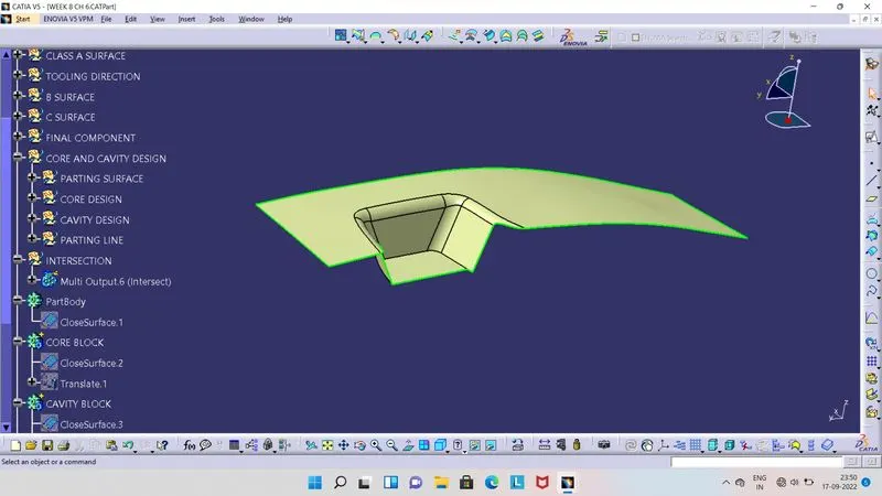
- Class C Surafce
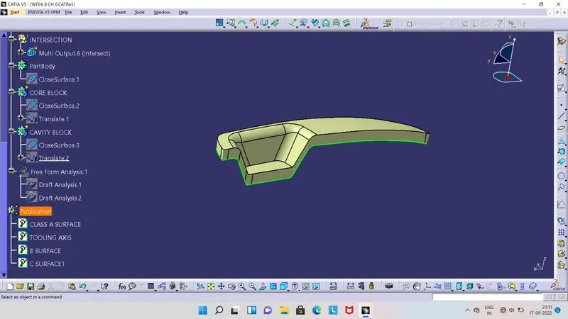
- Class A, B and C joned surfaces.
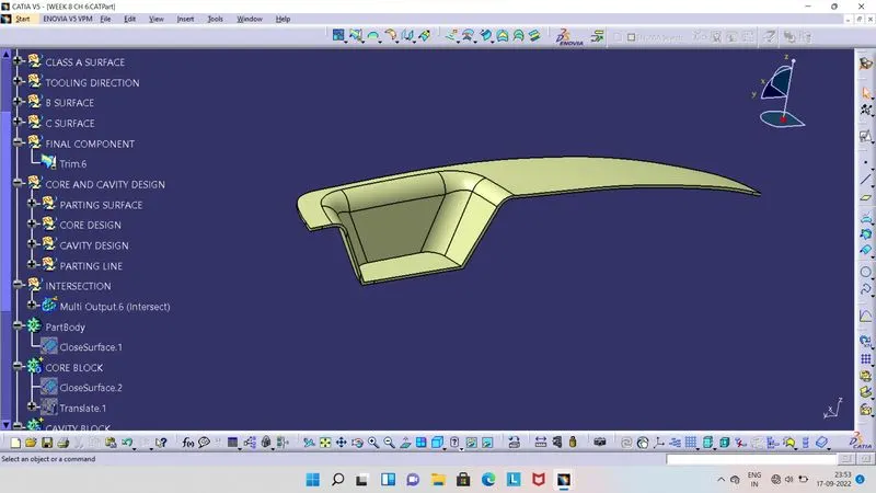
- Final Plastic Component .
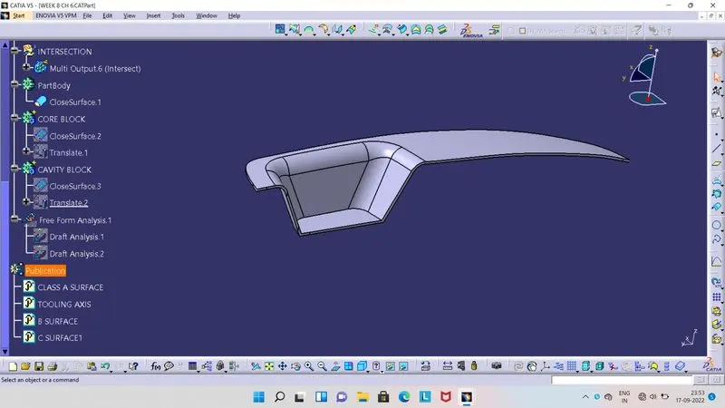
- Draft Analysis .
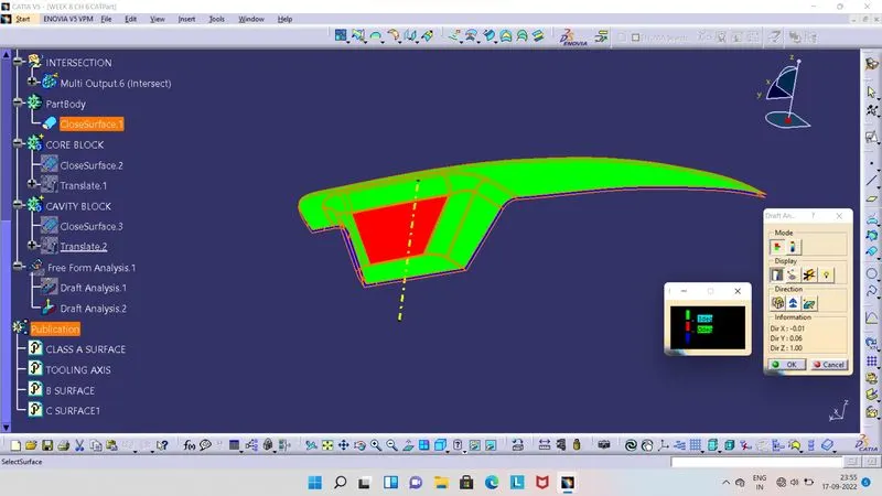
- Before doing Draft Analysis, ensure that our component is in the material view mode.
- Then select Feature Draft Analysis tool, so as shown in above image at the right side screen,2 boxes will appear and in the tree structure, Draft Analysis.2 like added.
- So, now we have to click on compass, so compass will be seen to us on screen. Align this compass with Tooling Axis, then click on lock symbol and then click on final plastic component.
- Final plastic component get colour on it.
- Green colour indicates the draft angle is above 3 degrees.
- Red colour indicates the draft angle is between 0 to 3 degrees.
- blue colour indicates the draft angle is below the 0 degrees or negative.
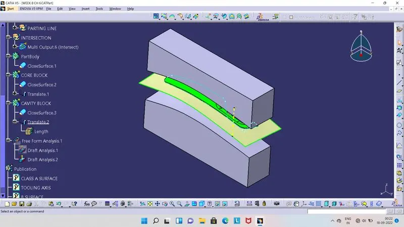
- Screenshots of the core and cavity blocks in various orientations.
- For Core design, we have to first create Parting Surface.
- Parting Surface is surface, which parts the Core and Cavity. For its creation we need Class B and C surface, first we have to create intersection line between Class B and C Surface, so we get Parting line.
- By using this line we can split the Class B Surface, which is our Parting Surface.
- By having parting surface with component, we create rectangle sketch and extrude it, then trim this exruded surface with this parting surface with component. So above portion which we get is Core.
- Now we can make it as a solid by using Close tool.
- Parting Surface with final component :
- In the below image, yellow colour surface is a Parting surface and between its component with green and red colour.
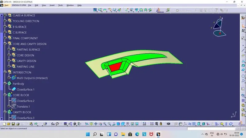
- Parting Surface :
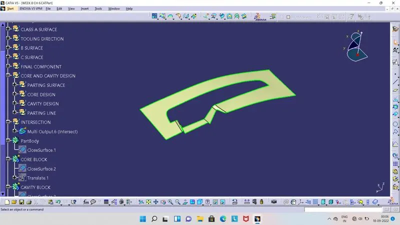
- Parting Line :
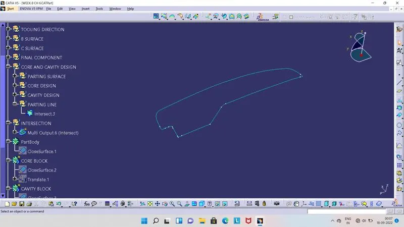
- In below image sky-bule colour doted line is parting line.
- It is line which separates the component and Parting surface.
- Final component with Draft Analysis.
- Core Block :
- Its a movable part in molding process.
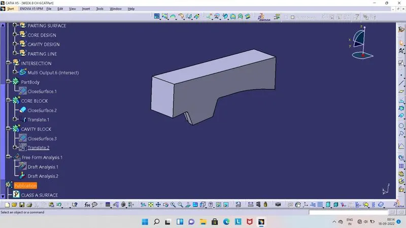
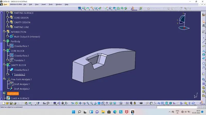
- Cavity Block :
- Its block which is fixed or not movable in moulding process.
- For Cavity Design, we will extrude the same recatngle sketch which we had created for Core design. Then trim this extruded surface with Class B surface, so below part which we will get its our Cavity Block.
- We have to fill the lower portin of the extruded surface to make it close surface and then solid from it.
- Isometric View of Core and Cavity Block :
- Front View :
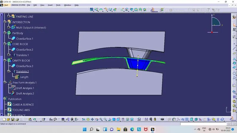
- Side View :
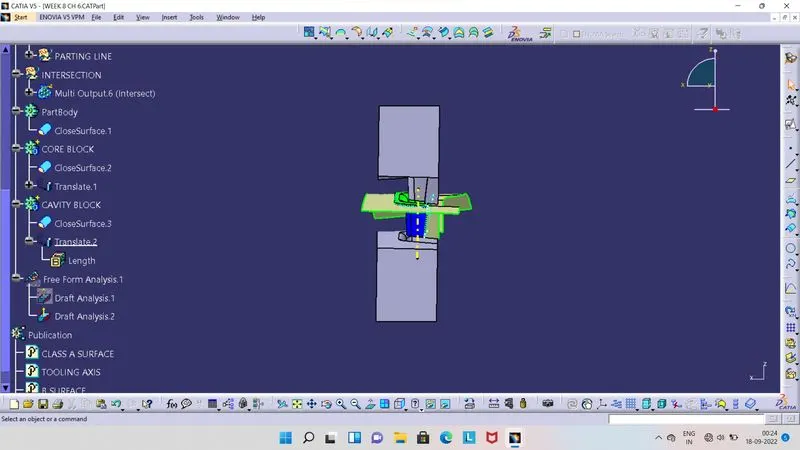
- Top View :
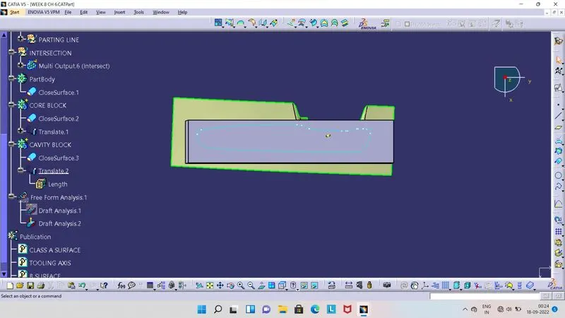
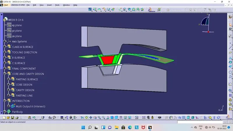
- Intersection between Core, Cavity, Parting Surface and Final Component with respect to ZX Axis.
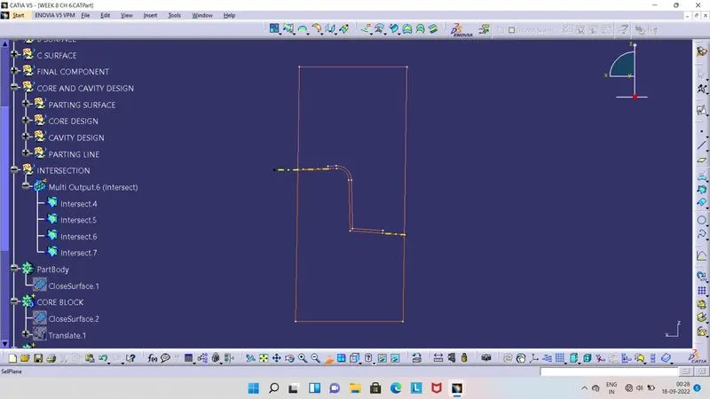
- In this image, we can see that, Pink colour block at top is represents the Core Block.
- Orange colour at lower portion, represents the Cavity Block.
- Yellow colour dashed line represents the Parting Surface.
- There is a gap between Core and Cavity block, in this gap molten material is fed and after solidification it will be ejected, which is our required component.