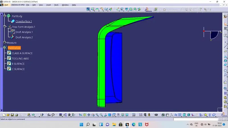
Week 8 - Challenge 3 - Coin Holder Design
- Screenshots of the Draft analysis report for the given Class-A surface.
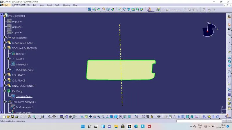
- For Draft Analysis Tooling Axis ie required.
- So for this component, we have to first exract base surface and take point at center of it.
- As this base surface is flat and surrounding with Bin Walls, so we can make line normal to this base surface using center point.
- Its our Tooling Axis.
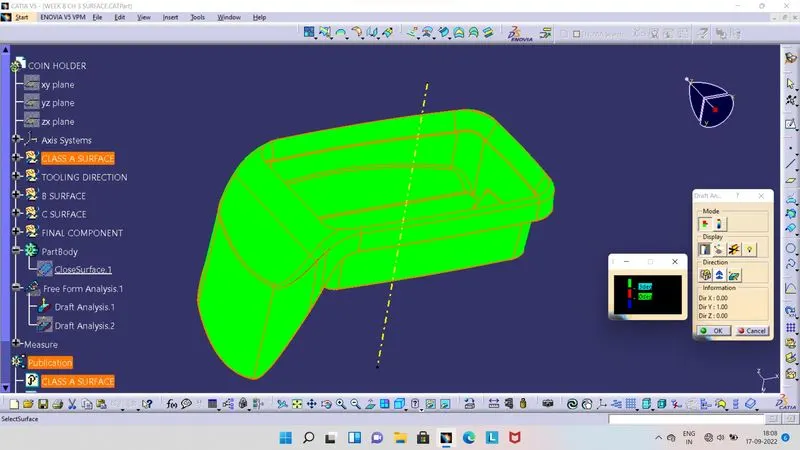
- Once we create Tooling Axis, then we can go for the draft analysis.
- Before Draft Analysis, ensure that our component is in the material view mode.
- Then select Feature Draft Analysis Tool, so we will get 2 boxes as shown in above image at right side.
- From there we have to click on compass, so compass will seen on screen. Then align this compass to our Tooling Axis by moving it.
- As compass is align with Tooling Axis, click on lock symbol and then click on Class A Surface.
- Class A surface now get colour on it.
- Green colour indicates, Draft angle is above the 3 degrees.
- Red colour indicates, Draft angle is between 0 to 3 degrees.
- Blue colour Indicates, Draft angle is below 0 degrees or negative.
- Screenshots of the Draft analysis report for the final plastic component.
- Class B Surface :
- Its Offset surface of Class A Surface.
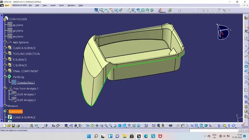
- Class C Surface :
- Its a Surface which join the Class A Surface and Class B Surface.
- Here C Surafce is perpendicular to the Tooling Axis, so we have sweep the boundary of Class A Surface at 90 degrees with reference surface.
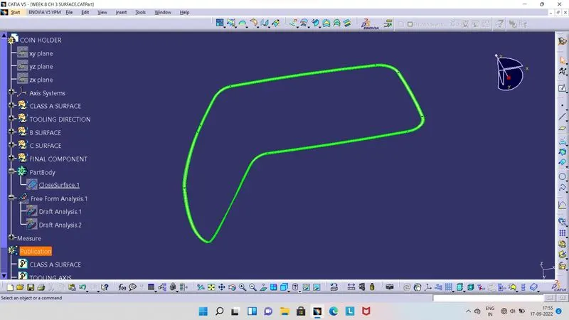
- Class A, B and C joined Surface.
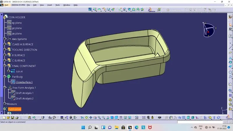
- Final Component :
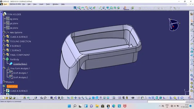
- Draft Analysis of final palstic component :
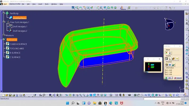
- Before Draft Analysis, ensure that our component is in the material view mode.
- Then select Feature Draft Analysis Tool, so we will get 2 boxes as shown in above image at right side.
- From there we have to click on compass, so compass will seen on screen. Then align this compass to our Tooling Axis by moving it.
- As compass is align with Tooling Axis, click on lock symbol and then click on final plastic component.
- Final plastic component now get colour on it.
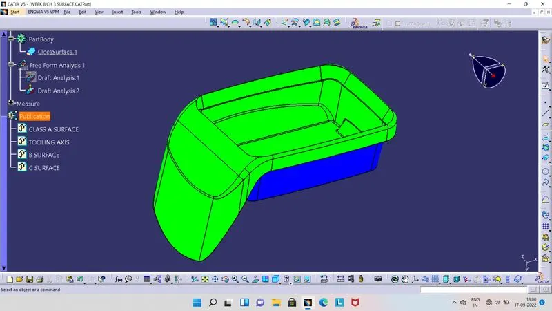
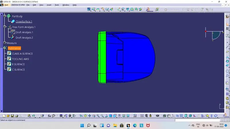
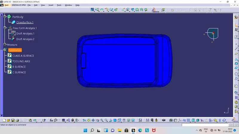
- Green colour indicates, Draft angle is above the 3 degrees.
- Red colour indicates, Draft angle is between 0 to 3 degrees.
- Blue colour Indicates, Draft angle is below 0 degrees or negative.
- Screenshots of the solid model with the proper color code of the draft angle in various orientations.
- Isometric View :
- Front View :
- Side View :
- Top View :