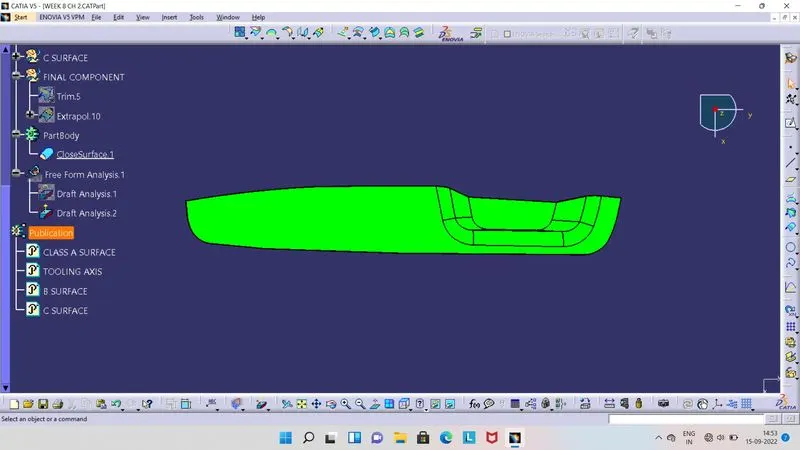
Week 8 - Challenge 2 - Switch Bezel Design
- Screenshots of the Draft analysis report for the given Class-A surface.
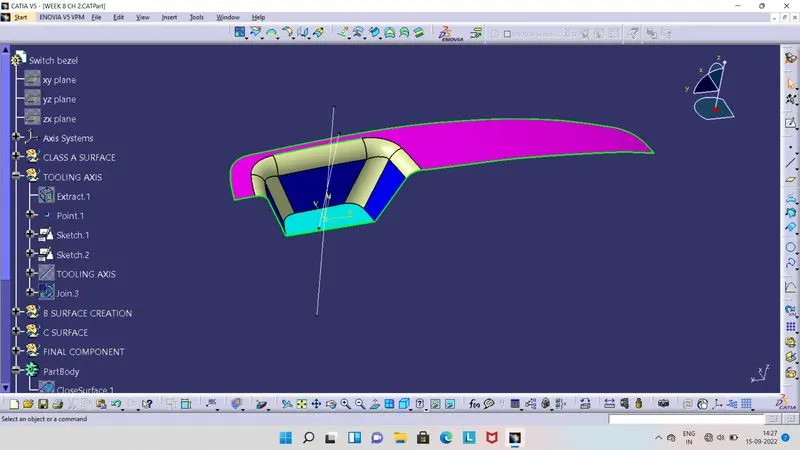
- For Draft Analysis, we need Tooling Axis. So here we will take point at center of the base of the Class A Surface by extracting base.
- For get respective profile, we take Axis system and by performing in two individual sketches, we will create two bisecting lines, one at ZY direction and another one at ZX direction.
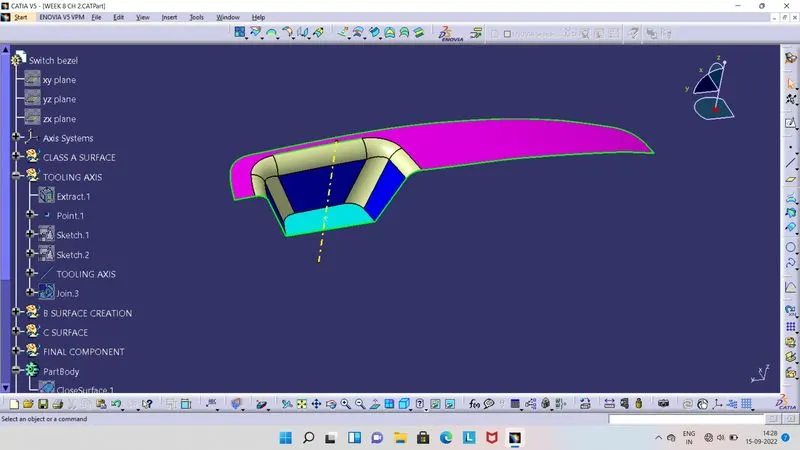
- So for to get main Tooing Axis, we will take Bisecting Line type and select two lines which we have created and center point.
- So as shown in image, we will get Tooling Axis.
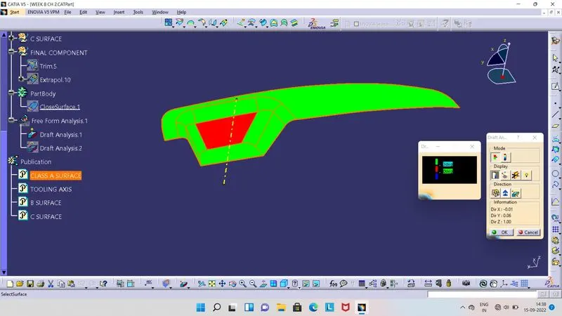
- As we get Tooling Axis, we can do Draft Analysis.
- Before do the Draft Analysis, we have to ensure that, we have kept component into material view mode.
- Then click on Feature Draft Analysis tool, so we get two boxes shown in above image at the right side.
- From there we have to select compass and this compass will be seen at screen, then we have to align this compass with Tooling axis, by moving compass.
- Once compass is align with Tooling Axis, then click on lock symbol and then click on Class A Surface. So we get Colour on surface.
- Green colour indicates, that draft angle is above 3 degrees.
- Red colour indicates, that draft angle is between 0 to 3 degrees.
- Blue colour indicates, that draft angle is below the 0 degrees or its negative.
- Screenshots of the Draft analysis report for the final plastic component.
- Class B Surface :
- By extracting and then performing several operation by using tools and offset the surfaces from Class A Surface, we will get Class B Surface.
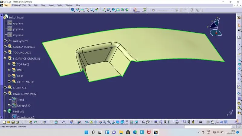
- Class C Surface:
- By Creating Boundary of Class A Surface and then using Sweep tool, we can create C Surface by joining with Class A Surface.
- So Class C Surface is a joining surface between Class A Surface and Class B Surface.
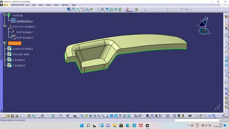
- Final Plastic Component :
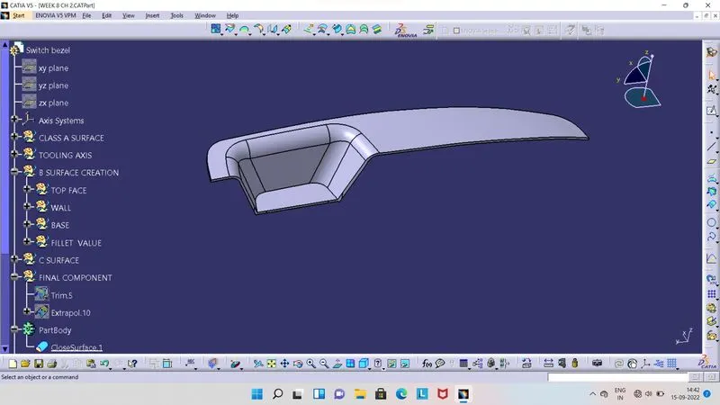
- Drfat Analysis for Final Plastic Component :
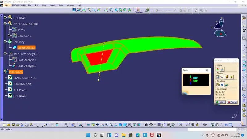
- Before do the Draft Analysis, we have to ensure that, we have kept component into material view mode.
- Then click on Feature Draft Analysis tool, so we get two boxes shown in above image at the right side.
- From there we have to select compass and this compass will be seen at screen, then we have to align this compass with Tooling axis, by moving compass.
- Once compass is align with Tooling Axis, then click on lock symbol and then click on Fianl Plastic Component. So we get Colour on surface.
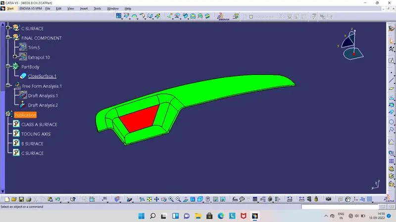
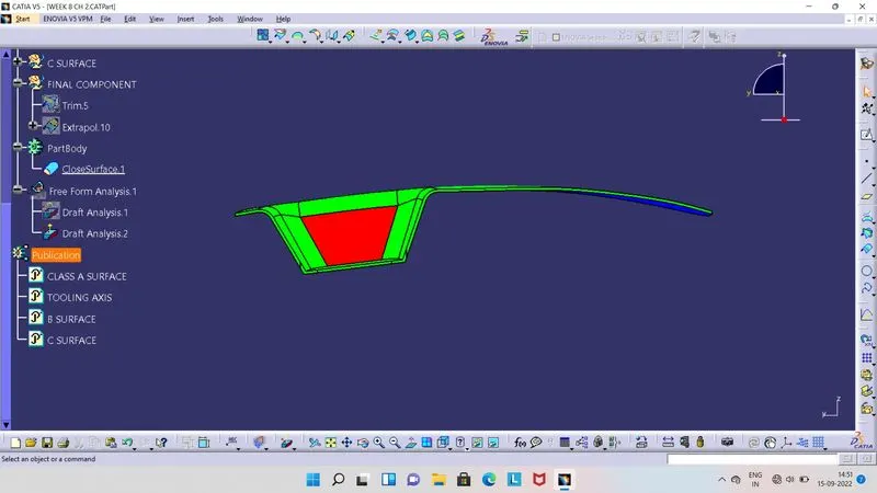
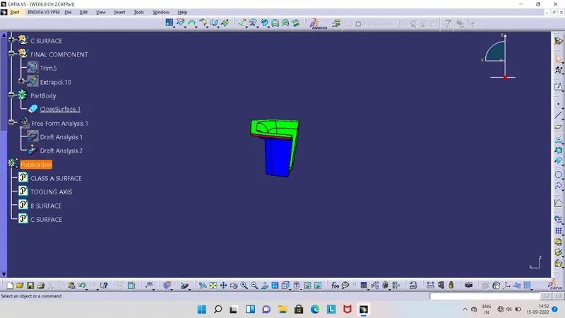
- Green colour indicates, that draft angle is above 3 degrees.
- Red colour indicates, that draft angle is between 0 to 3 degrees.
- Blue colour indicates, that draft angle is below the 0 degrees or its negative.
- Screenshots of the solid model with the proper color code of the draft angle in various orientations.
- Isometric View :
- Front View :
- Side View :
- Top View :