Wiring harness routing & packaging Rules Week 3 Challenge
Wiring Harness Routing and Packaging Rules
In this challenge, We are first going to define a mechanical cad component electrically by setting up the geometrical parameters and then using the Electrical Pat Design workbench we will define the electircal support.
In order to set the geometrical parameters for defining the electrical support, we need to create an Entry Point and Plane, Exit Point and Plane and a Base Plane as shown in the figure.
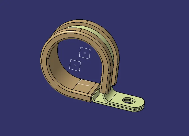
Once all the points and planes are created, we are ready to define this part electrically.
Click on Define Support Part in the electrical part design workbench and selet the entry point and plane under the first plane definiton. Similarly, Select the exit plane in the second plane definition and base plane in the base plane definition respectively.
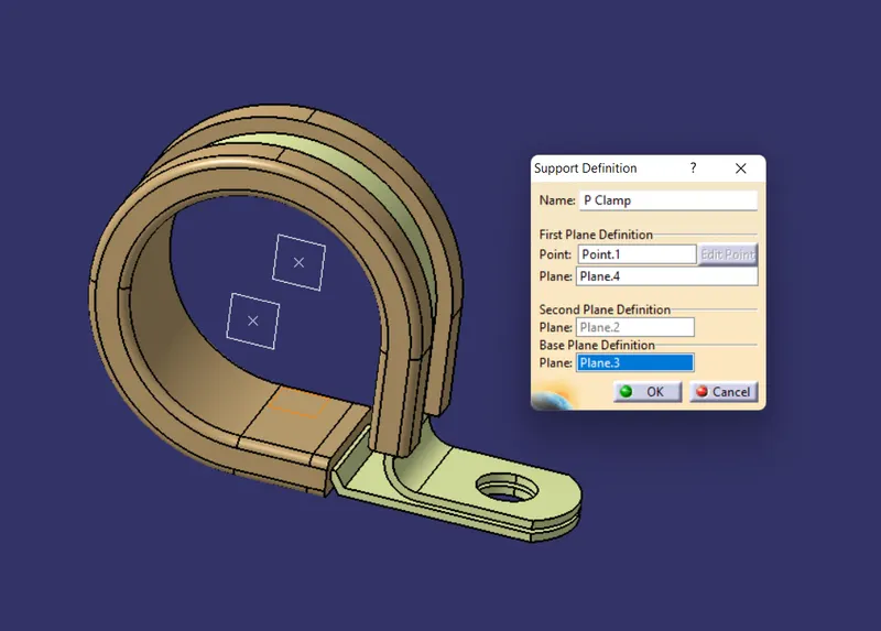
while defining the part as electrical support an engineer has a provision of defining two entry side hence we need to define the support again.
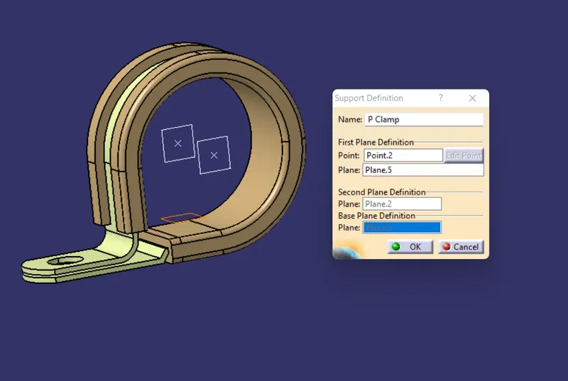
The part is now completely defined as an electrical part. the part can now be saved under the catalogue for reference which helps the engineer to avoid creating it again during the routing process.
Backshell
Backshells are plastic moulded parts used at the wire entry side of connectors either for protection or to improve the aesthestics of the harness.
These are not mandatary parts of a wiring harness and are always optional. It is mainly driven by the cost and requirement of the wiring harness engineer.
Defining Backshell is pretty simple ideall, we first need to set up the geometrical parameters that we use to do for all electrical components.
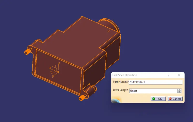
Once parameters are set define this point in Electrcal Part Workbench using the command Define Back Shell.
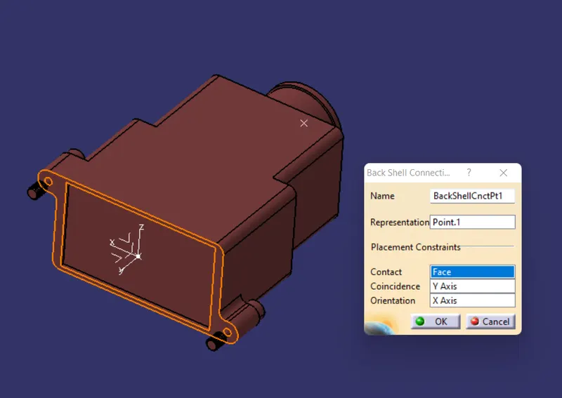
Now define the backshell connection point using the point and axis created at the mating side of the shell.
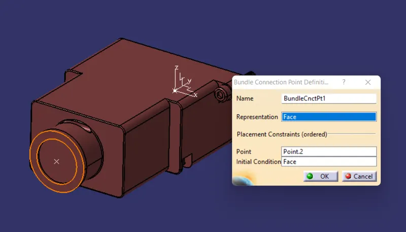
Then define the bundle connection point using the point and surface located at the entry side of the bundle.
A catalogue for the same can be created for reference.
Corrugated Tubes
Corrugated Tubes, Convolutes, Sleeves and many other types of coverings are used to protect the wiring harness.
The graphical representation of these coverings is applied on bundels.
These tubes can easily be created in CATIA using Electical Part Design Workbench by giving appropriate dimensions to them. Create a new part, select define protection covering and click on the part bodyor file name under the model tree.
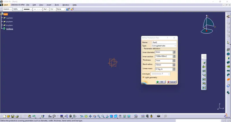
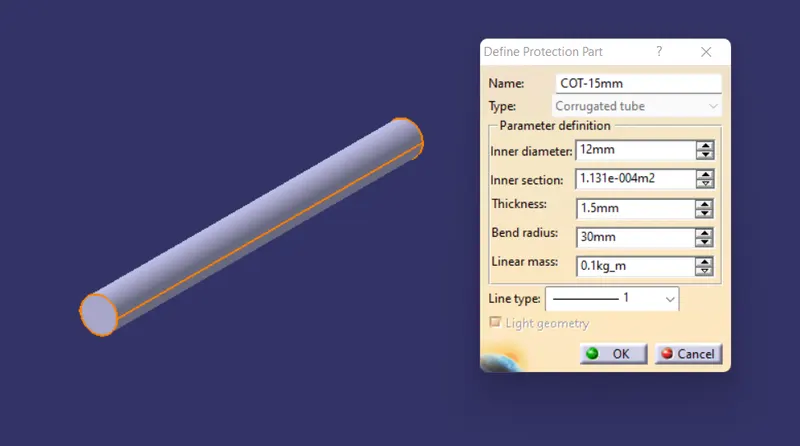
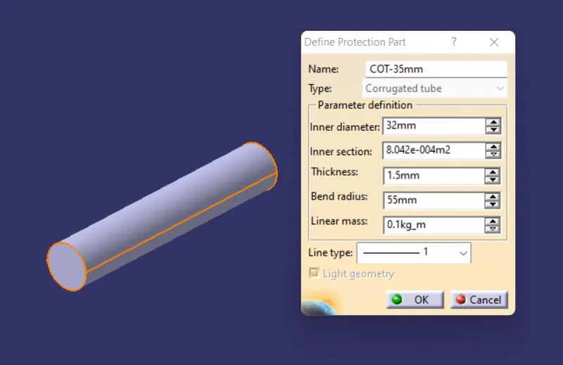
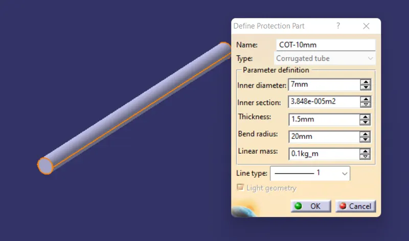
The dimensions that are required to create COT Tubes are inner and Outer dia. Thickness and bend radius.
The bend radius is decided based on the flexibility of the tube. Generally the bend radius will be 1.5 times the outer dia of the tube.
Depending on the bundle dia the COT outer dia is decided. The dia for the Tubes must be greater or equal to the bundle dia.
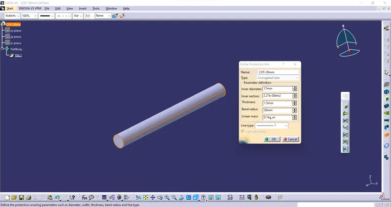
In this challenge we have created multiple tubes with different dimensions and saved them in a catalogue under the COT Tubes family.
COT-15mm
COT-35mm
COT-10mm
COT-5mm
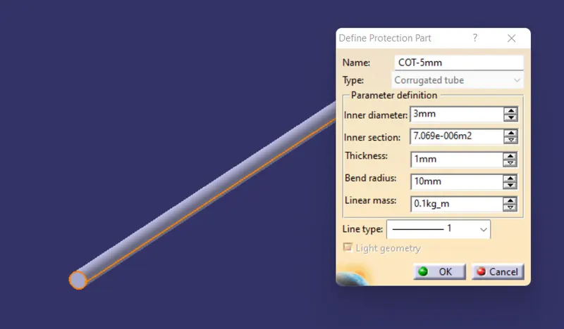
Corrugated Tubes or simply called as COT Tubes are created and saved in a catalogue. It is necessary for an engineer to save the tubes in a catalogue in order to use them during the harness process.