Door Arm Rest Week 8 Challenge
AIM :-
To Draft a Door Arm Rest from the given Class A Surface by adding of 2.5mm thickness.
TOOLING AXIS :-
Creating Tooling Axis is used to draft given component and it is also used gives direction to mold opens, Here using bisecting method to create Tooling direction.
- First visually check given Class A surface for to find out tooling axis which is cover all faces. Here in this case viewing from Z direction we can clear the face in tooling.
- Most of the cases we create the point in holes and pocket of the part, because the holes and pockets is to create a problems when we do the draft analysis. so we create a point in mid of the hole.
- First extract the hole boundary and fill it with fill cammand after crate a point on hole filled surface at the center.
- With help of that point creat a Axis System. Then we finding out the tooling axis in X direction. For that intersect command is used to get the boundary in X direction.
- Then we crate the lines on the walls and bisect theses two lines with the line bisect command. and a bisect line is created.
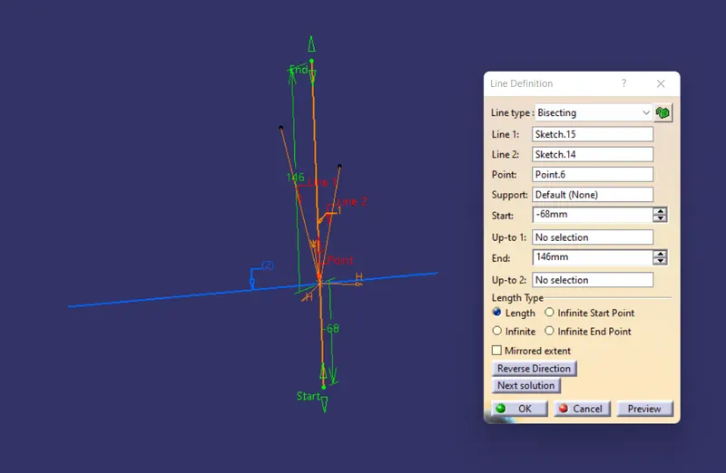
- But pocket wall was not cleared, so we need to create the side tooling axis to clear the pocket walls.
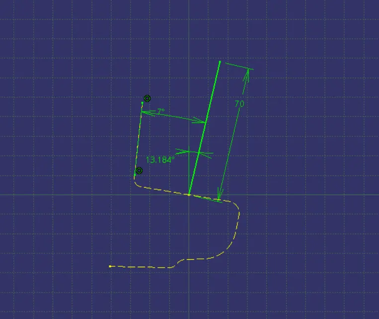
and then publish the tooling axis.
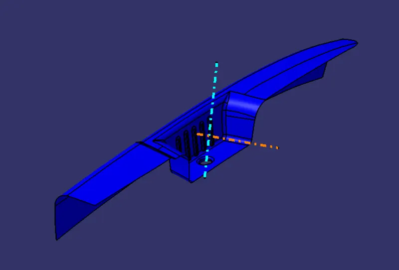
Class B surface creation:-
First divide given Class A surface into three parts like first half, second half and pocket.
For the first half extract long wall at back side fo the door and top flat wall. After that untrim them with the help of untrim command, if those untrim walls are intersects lets trim its with trim command or not then expolate by point continuity propagation is used to make those surfaces are intersection. Now, the thickness of the final components is 2.5mm so this obtained surafce is offset below by 2.5mm.
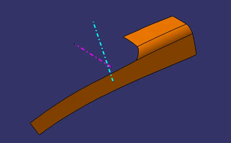
For the second half extract top flat walls of given Door Arm rest. After that untrim them with the help of untrim command, if those untrim walls are intersects lets trim its with trim command or not then expolate by point continuity propagation is used to make those surfaces are intersection. Now, the thickness of the final components is 2.5mm so this obtained surafce is offset below by 2.5mm.

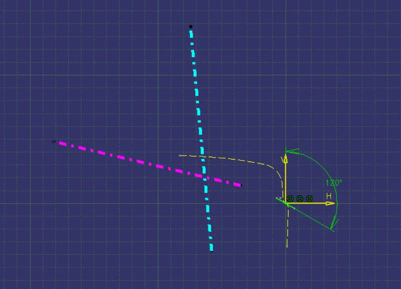
For the attachment curve, use multi-extract command to extract the curved line and creat an axis system on that extracted cureve line and draw a inclined line.
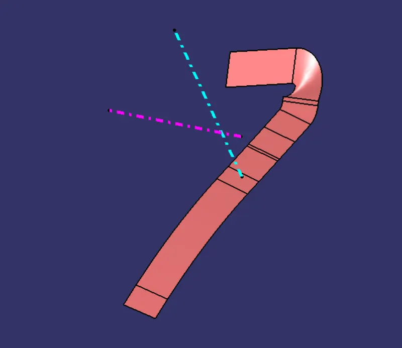
After that use sweep command to create surface with help of inclined line along with multi-extracted curved line. Now, the thickness of the final component is 2.5mm so this obtained surface is offset below by 2.5mm.
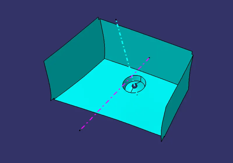
For the pocket extract all walls. After that untrim them with the help of untrim command, if those untrim walls are intersects lets trim its with trim command or not then expolate by point continuity propagation is used to make those surfaces are intersection. Now, the thickness of the final components is 2.5mm so this obtained surafce is offset below by 2.5mm.
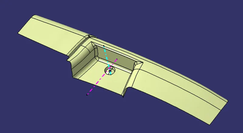
And then trim these all surfaces and give the fillets to Class B surface.
CLASS C SURFACE CREATION:-
The C class surface will be created using the sweep command and for that, the Boundary lines are obtained from the A-class surface. The curv part is then smooth by some value for ease in sweeping. Then, all boundary lines are sweep with draft direction since all the surfaces must have a draft angle of 3 degrees. Also, the tooling axis is used as the direction of the sweep.
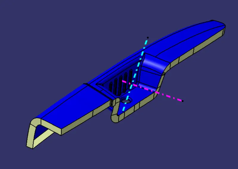
Next, the swept surfaces are joined with the A-class to form a complete A and C surface. (note merging distance is kept at 0.003mm to avoid any gaps)
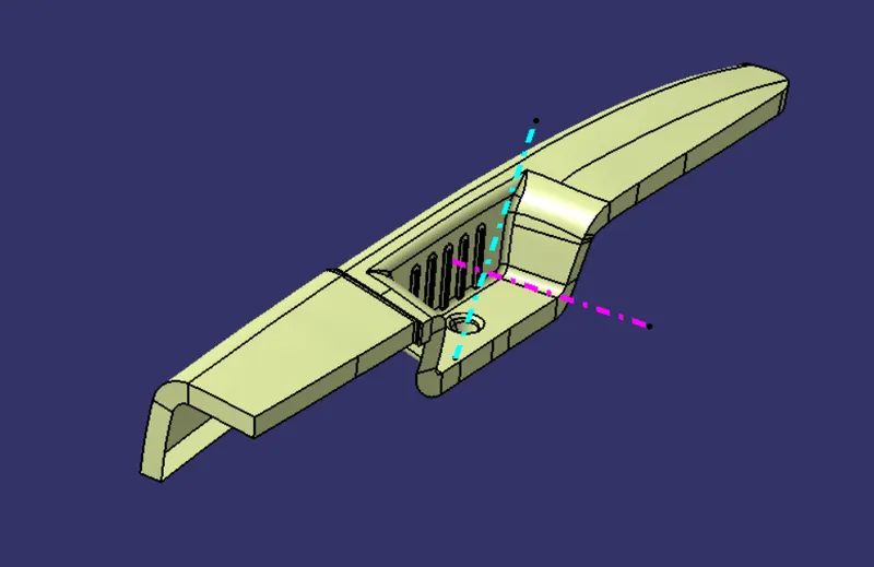
Lastly, the A and C is trimmed with the B surface to get the final baseplate component. This obtained surface is then thickened in part design.
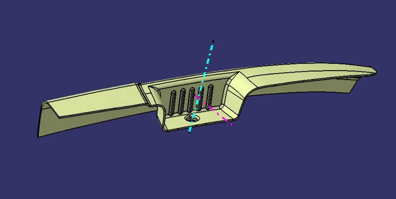
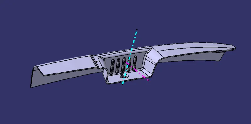
DRAFT ANALYSIS:-
The Draft Analysis command enables you to detect fi the part you drafted will be easily removed. This type of analysis is performed based on color ranges identifying zones on the analyzed element where the deviation from the draft direction at any point, corresponds to specified values.
- To perfrom the draft ananlysis the view parameters are first set to material mode.
- Then go to insert -analysis-feature darft analysis, the fallowing window will be appread
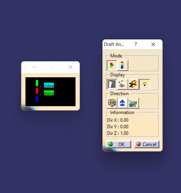
- First, select the axis system and drag the axis system to the tooling axis and lock the orientation. This axis system defines the draft direction according to the tooling axis.
- Switch on the color scale and set the draft value 3 degree using colour scale. and it will be displayed in green color. Any draft angle below 3 degrees will be shown in red color.
- Now select the running point tool to measure the draft angel at the various locations
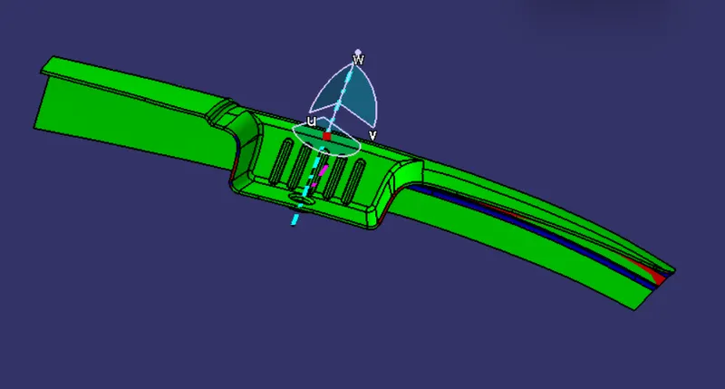
this tooling axis is not cleared the back side wall faces. so we created the side core axis for clear it.
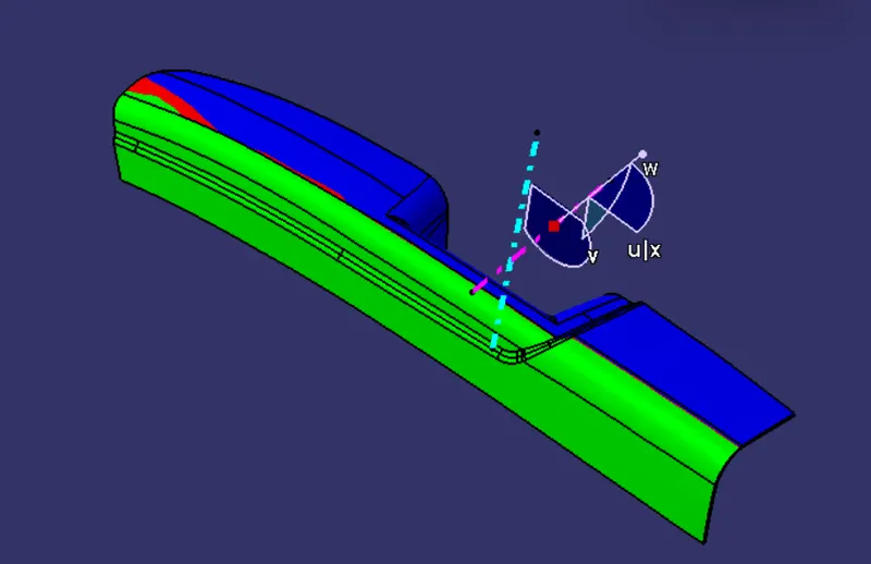
RESULT:-
The Class B and C surfaces are created from the Class A and trimmed these surfaces to form a part body having 2.5mm thick. and the draft analysis also done for the final component.