Week 8 - Challenge 4 - Coin Holder Design
AIM:-
To Draft a COIN HOLDER from the given Class A surface by adding of 2.5mm thickness.
TOOLING AXIS:-
Creating Tooling Axis is used to draft given component and it is also used given direction to mold opens.
- First visually check given Class A surface for to find out tooling axis which is cover all faces.
- Here the coin holder faces are stright so we can give tooling axis perpendiculer to base surface because the walls are stright if walls are have inclined we can choose other method like bisecting.
- Extract the base surface and create a point on center of extract base surface by using on surface point option.
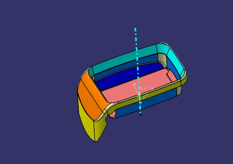
CLASS B SURFACE CREATIION:-
First divide given Class A surface like base, side walls, top walls, outer flange.
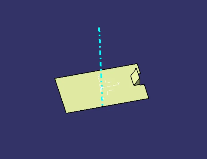
For the Base, extract the base surface and untrim it. after that by using extraplate command expand the base surface and offset that with 2.5mm.
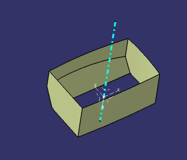
For the Side Walls, extract all side walls and untrim it. After that using extraplate command expand the all extracted walls upto all walls are interseted and trim them.
For the Top walls, use multisection command extract all walls and extraplate it upto coinside with side walls.
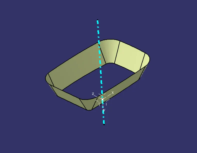
For the Outer flange, Here the outer flange is divided into two parts like walls and curved surface. First extract the walls use multisection command and extraplate it. After that extract the curved surface and join them and extraplate it. After trim together using trimed command.
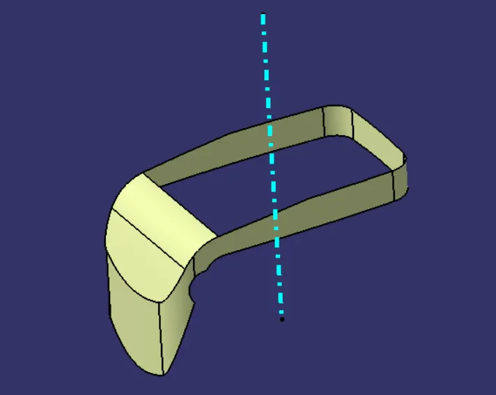
After create surfaces of all divided faces trim them together with help of trim command and give fillet values.
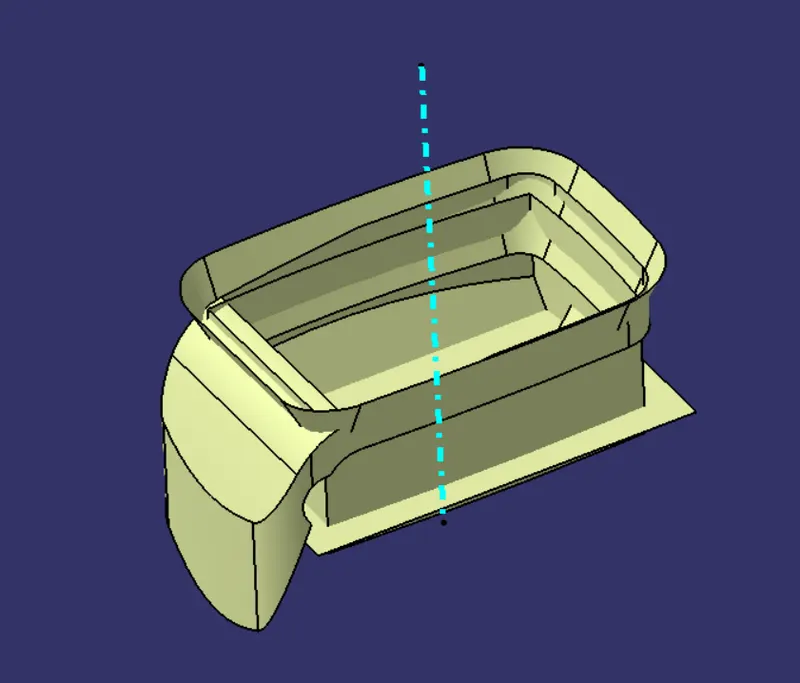
Class B surface
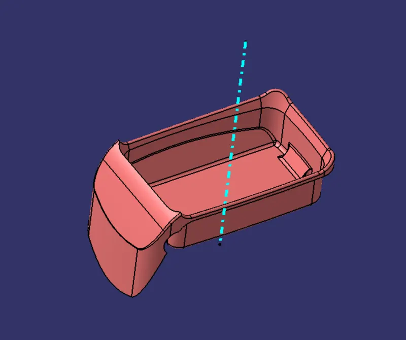
CLASS C SURFACE CRATION:-
Here C surface is create using sweep command with help of surface reference for that creat boundary lines from Class A surface and extract outer flange surface with help of multisection command and sweep it with refernce surface.
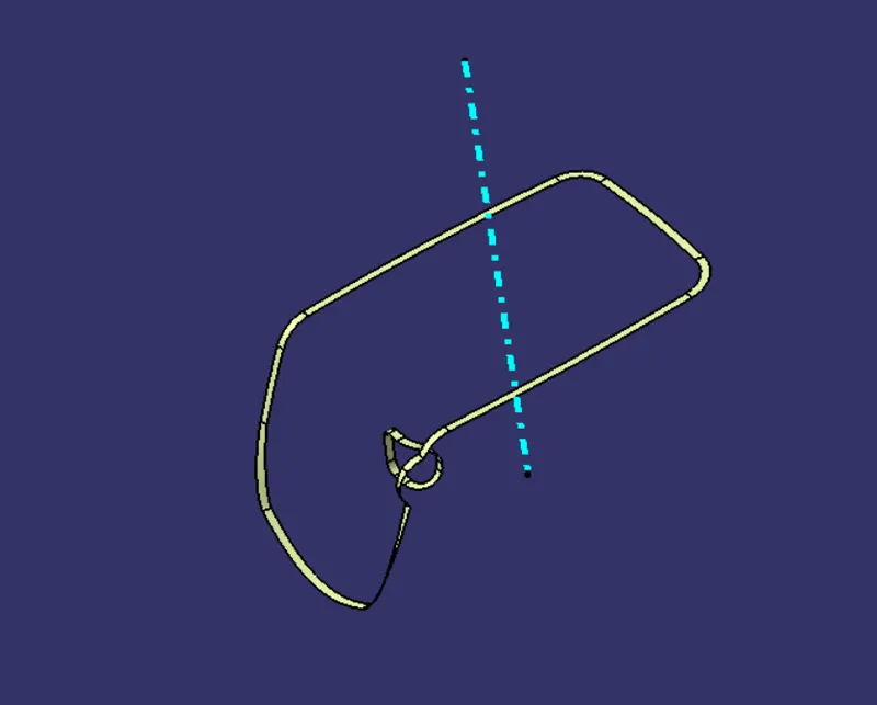
And join sweep with Class A surface and trim with Class B suface.
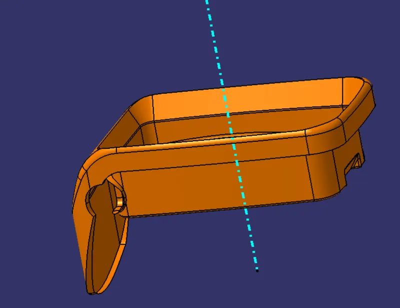
Closed surface
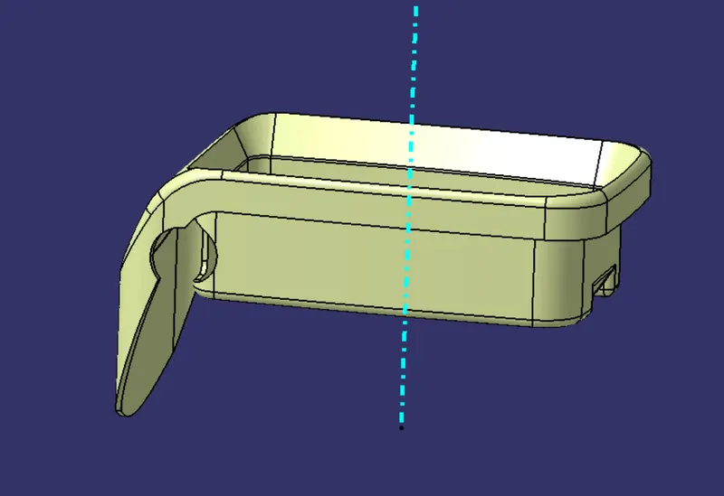
Solid body
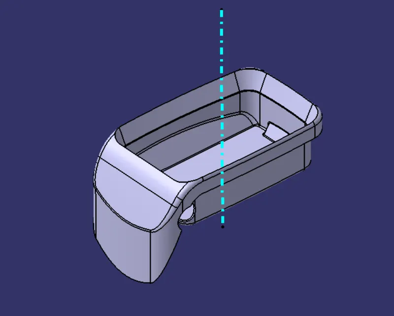
DRAFT ANALYSIS:-
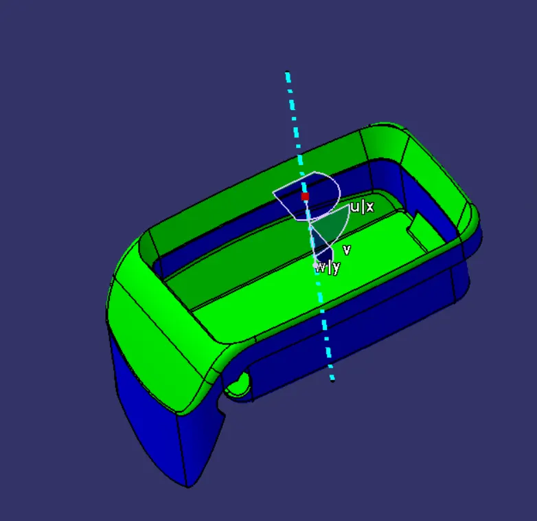
The Draft Analysis command enables you to detect if the part you drafted will be easily removed. This type of analysis is performed based on colour ranges identifying zones on the analyzed element wherethe deviation from the draft direction at any point, corresponds to specified values.
- To perform the draft analysis the view parameters are first set to material mode.
- Then go to insert-analysis-feature draft analysis, the fallowing window will be appread
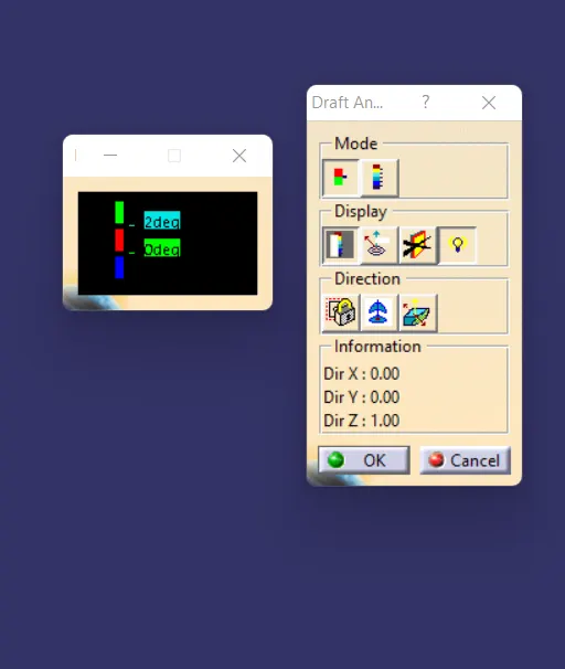
- First select the axis system and drag the axis system to the tooling axis and lock the orientation. This axis system defines the draft direction according to the tooling axis.
- Switch on the colour scale and set the draft value 3 degree using colour scale, and it will be displayed in green colour any draft angel below 3 degrees will be shown in red colour.
- Now select the running point tool to measure the draft angle at the various locations
RESULT:-
The Class B and C surfaces are created from the Class A and trimmed these surfaces to form a part body having 2.5mm thick and the draft anaylsis also done for the final component.