Wiring harness routing & packaging Rules- CATIA V5
CATIA (Computer-Aided Three-Dimensional Interactive Application) is a powerful and comprehensive computer-aided design (CAD) software suite developed by Dassault Systèmes. CATIA has different workbenches in which Electrical workbench provides tools for designing and managing electrical systems, including wiring harnesses. A wiring harness is a collection of wires, cables, and connectors that transmit electrical power and signals within a system or device.
Designing wiring harnesses using CATIA;
v Product Structure: In CATIA, a wiring harness is typically designed within the context of a larger product structure. The product structure defines the hierarchical organization of components and subsystems within a product.
v Electrical Workbench: The Electrical workbench in CATIA is specifically tailored for electrical system design, including wiring harnesses. It allows engineers to create, manage, and document electrical components and systems seamlessly.
v Electrical Components: CATIA enables the creation of various electrical components such as connectors, terminals, splices, and other elements that make up a wiring harness. These components are modeled in 3D to represent their physical characteristics accurately.
v Wiring Routing: The software provides tools for routing wires along specific paths within the product structure. Engineers can define the routing paths for wires, taking into account factors such as electrical requirements, spatial constraints, and manufacturability.
v Connectivity: CATIA ensures that proper connectivity is maintained between electrical components. This includes accurately placing connectors, terminals, and splices and ensuring that the wires connect to the appropriate points.
v Visualization and Simulation: CATIA allows users to visualize the wiring harness in 3D, facilitating a comprehensive understanding of how the harness interacts with other components in the product. Additionally, simulation tools may be used to analyze the electrical behavior and performance of the wiring harness.
v Validation and Checks: The software includes validation tools to check the design integrity, detect clashes, and ensure that the wiring harness meets specified standards and requirements.
v Documentation: CATIA facilitates the creation of detailed documentation for the wiring harness design, including drawings, reports, and other documentation necessary for manufacturing and assembly.
v Integration with other Disciplines: CATIA is part of a collaborative design environment, allowing seamless integration with other disciplines such as mechanical, structural, and systems engineering. This ensures that the wiring harness design is synchronized with the overall product development process.
v Data Exchange: CATIA supports the exchange of data in various formats, facilitating collaboration with other CAD systems and tools used throughout the product lifecycle.
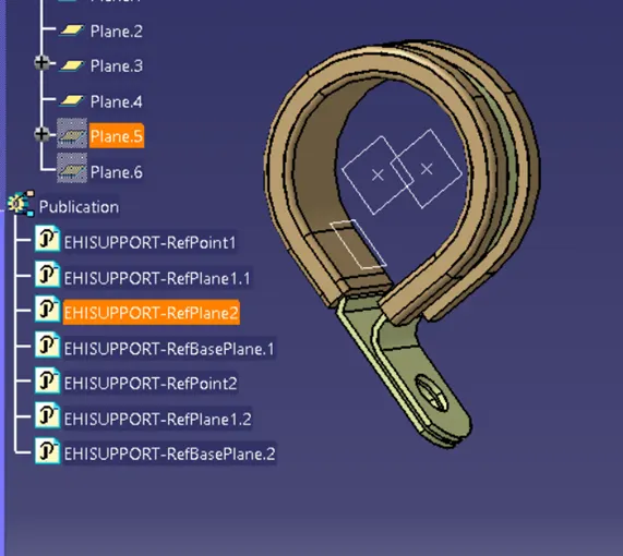
To familiarize with the CATIA workbench, let’s work with an electrical support component. Here, we take a P-Clamp which is used to fasten and secure wiring along the harness.
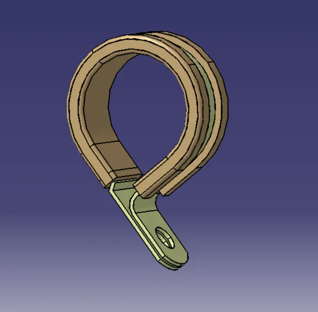
We must use the Part Workbench of the CATIA where we create the reference geometry for the electrical definition. The first step is to download the IGES file and convert to CATIA part file. The reference geometry here refers to the entry and exit points and base plane.
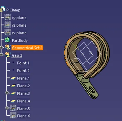
After the creation of points and planes taking sufficient relations from the CAD data of P-Clamp, we make use of the Electrical Part Workbench, where we define the part as Electrical Support. We map the reference geometry earlier constructed to Electrical exit and entry point twice to support symmetrical flow.
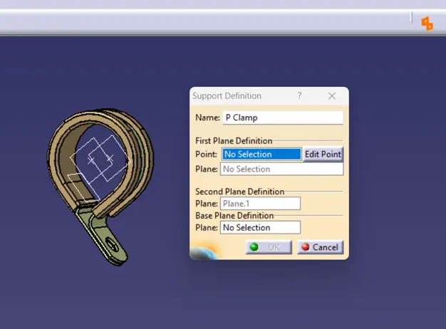
After the definition of the CAD file as Electrical Support Component, CATIA saves the electrical definition as Publications. From the data of publications, wiring harness is made possible.
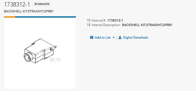
In the next example, we work on the CAD file of a Back Shell and the conversion of it to electrical component. The Back Shell is a protective device or accessory used in cable and connector assemblies. Its primary purpose is to provide strain relief, environmental protection, and shielding for the connection points in a cable or wiring harness. For this study, we are taking the CAD file of Tyco 1738312.
The Back Shell data is imported as IGES and converted to CATIA Part. As earlier, we have to work in the Part Workbench first to define the reference geometry.
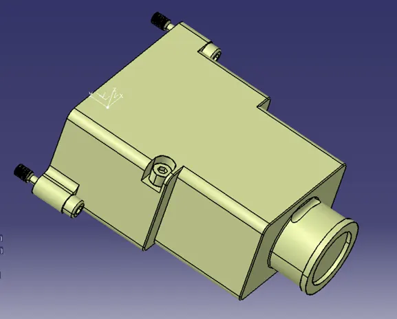
In the Part Workbench, we have to create the points for entry and exit appropriately for terminal connection and bundle entry. Here, we may need not create reference planes but rather an axis system for defining the orientation and mating of the Back Shell with the connector. After the creation of sufficient reference geometry we move to Electrical Part Workbench, in which we first define the CATIA part as Back Shell.
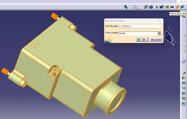
Next, we need two definitions, former being the connection definition with the connector and later being the bundle entry joint from the harness. These definitions are made using electrical connection point definition tools.
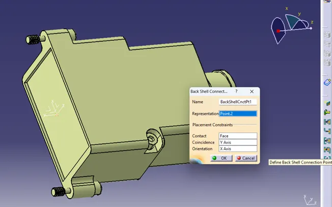
First, we define the Back Shell connection point that maps the axis and face of the CAD data. Next, we define the bundle entry point for the Back Shell, it takes the reference of the point we created and the face of the Back Shell where the bundle of wires is supposed to enter.
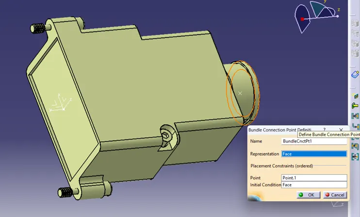
After the complete definition of the electrical Back Shell, the CAD file is now ready to be used as a Electrical Component in our wiring harness assembly.
Since we are creating bunch of electrical components it’s a good idea to store them in a catalog file, so that we can retrieve the electrical parts according their category.
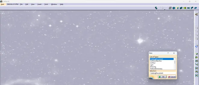
Now we have to define the catalog family and type, for these we need select “add family” and proceed with the naming and type as “conduit”, then proceed to save the catalog file in suitable folder.

Let’s move to creating corrugated tubes in CATIA Workbench. Corrugated tubes are tubular structures with a corrugated (ridged or grooved) surface. These tubes are designed to provide flexibility, protection, and routing for electrical wires, cables, and other similar applications. The corrugated design imparts flexibility and allows the tube to bend and flex without compromising its protective properties. It is essential that we design proper corrugated tubes for both safety and durability for our wiring harness.
For designing the corrugated tubes, first we have to enter the Electrical Part Workbench of the CATIA. Then we need to select the Protection Covering under Electrical Device Definition, on which we can edit our parameters of the corrugated tubes.
For example, the inner diameter of the COT_TUBE_15 is 12mm and thickness is 1.5 mm as per our project requirement. So similar data is entered in the Protection Covering definition.
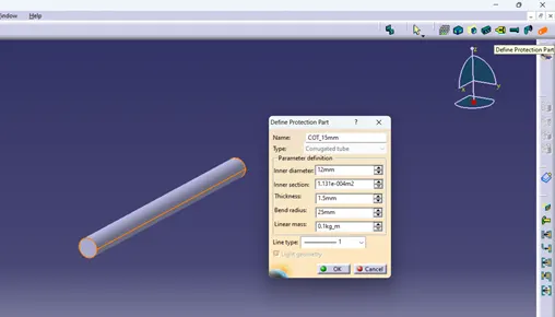
Similar steps are followed for each and every COT_TUBES as per our data. It is then essential to store this COT_TUBES under the catalog file for easier access.
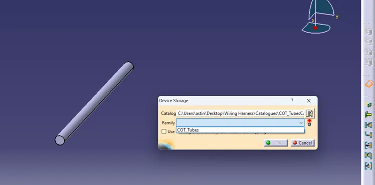
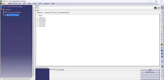
The electrical parts can easily be stored in catalog file using “store device” option in the Electrical Part Workbench. We have to select the proper family under the catalog file, here say we selected “COT_TUBES” on the catalog file named “COT_TubesCatalog.”
Attached below is the screen shot of the COT_TUBES ranging from 5 mm to 35 mm saved under “Slit COT” family inside a catalog file.