Base Bracket Design
BASE BRACKET COMPONENT DRAFTING ANALYSIS
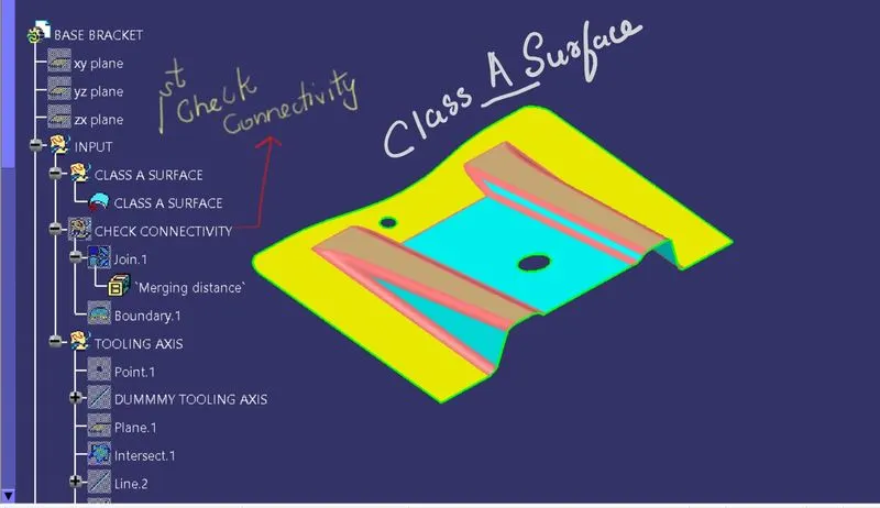
The given Class A surface is for most checked for connectivity and ensured proper geometry faces to work ahead.
The connectivtiy of class a surface can checked via join tool and boundary tool as per user's discreation.
Drafting of the component is necessary for proper ejection af molded componets and for ease of manufaturing. A minimun of 3 degree draft is required and while designing the components a maximum of 0.003mm limt is said to have for close tolerances like merging surfaces.
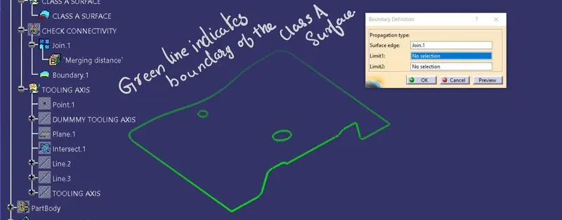
After checking for connective surfaces, we need to analyse the component on differet planes to identify the tooling axis. Tooling axis should be oriented in such a way that it offers minimum side core and under cut action and possible to provide draft to every component.
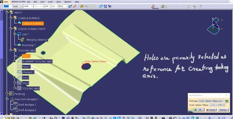
By selecting a point centre to circle, we have created a dummy axis on z axis. To create an actual tooling axis, we have to intersect the 3D surface to get its references in 2D curves in X plane and Z plane. These lines are taken as reference to build the tooling axis.
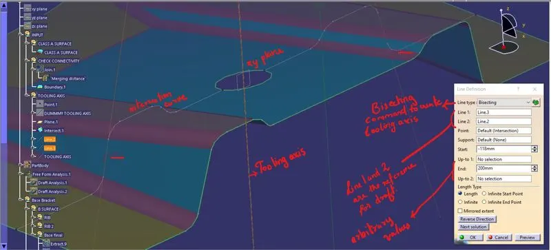
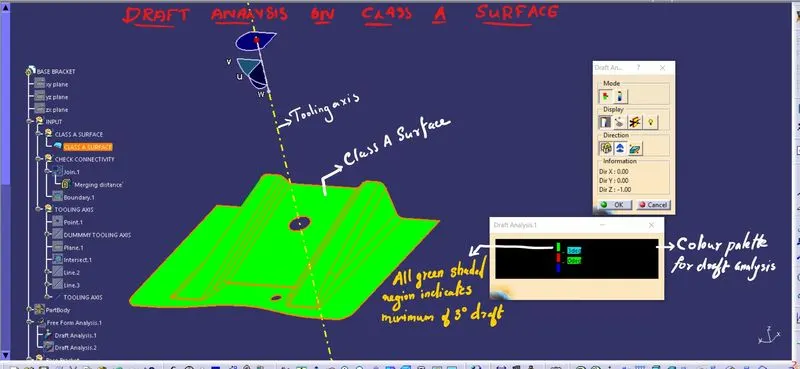
These are taken as input for creating a bisecting line between them and with proper shading tooling axis could be seen in much better condition for drafting and analysis in CAD. Daft analysis can be once done after creating the tooling axis. A first analysis is done on Class A surface for better understanding of slopes and geometry and to check whethers its manufacturable.
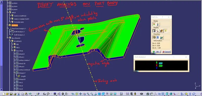
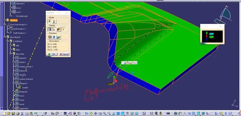
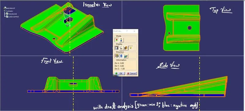
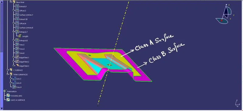
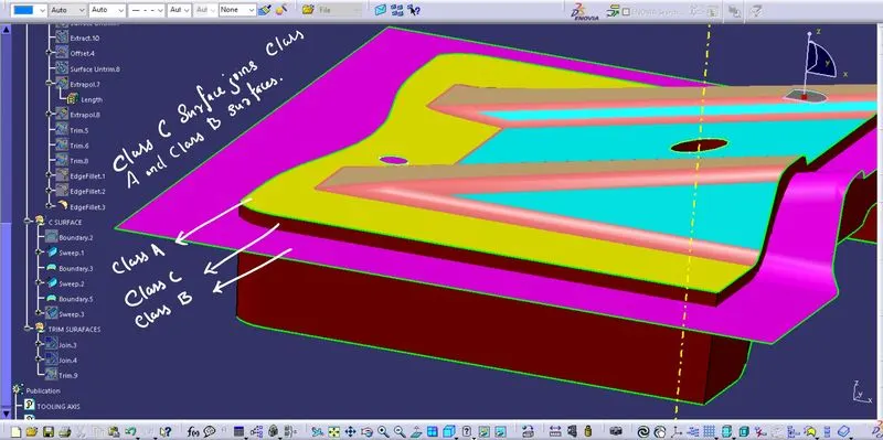
Draft analysis is done on the body finally after creating Class B and C surfaces. Creating a closed contour from thoses surfaces, using close body tool one can form solid component from theses sketches. Below images are screenshots of the solid model with the proper color code of the draft angle in various orientations (Isometric, Front, Side, and Top View).
CLASS B SURFACE:
CLASS C SURFACE:
DRAFT ANALYSIS WITH ANGLE INDICATION & COLOUR GRADING: