Sketching, Modelling, Assembly and Rendering - SolidWorks, Visualize
Report on Photo Realistic Rendering of American Chopper
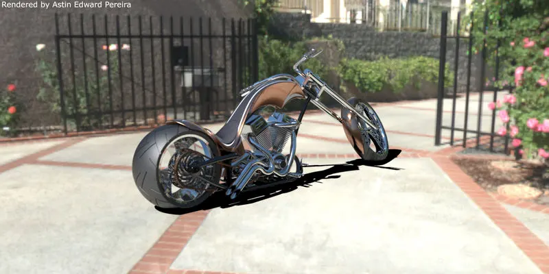
Introduction:
American Choppers are a kind of customized motorcycles emerged in California in the late 1950s, sometimes are built from scratch. Characteristics of choppers are its extended forks with an increased rake angle, stretched frames, larger than stock front wheels, frames without rear suspension etc. Cliff Sonny Vaughs is largely credited with designing and popularising choppers, one is known as "Captain America" chopper that starred in 1960s counterculture motorcycle movie "Easy Rider."
Orange Country Choppers is one among the American companies that produce choppers. The custom motorcycle manufacturer was founded in 1999 by Paul Teutl Sr. and has been designing and making choppers since then. OCC chose SolidWorks as its standard design platform, and testimonies that it accelerated time-to-market by 100%, shorten design cycles by 64%, cut development cost by 50% and eliminated seven rounds of prototyping.
SolidWorks is a CAD/CAE software product of Dassault Systemes who is the world's leading software solution provider in PLM, CAD, CAM, CAE industries.
It is very essential to have knowledge in 3D modelling and rendering for a design engineer and SolidWorks is a great tool to learn sketching, part modelling, assembling and rendering.
Objective:
- Part modelling of chopper parts
- Assembly of American chopper
- Rendering in Photoview360
- Photo realistic rendering in SolidWorks Visualize
Design Methodology:
- In Assembly:
Bottom-up and Top-down design
In bottom-up approach parts are created in separate part files and then are imported to assembly file to assemble the product, where else in top-down approach the parts are created within the assembly file and has the benefit of easily rebuilding the parts with respect to change in dimensions of other parts in the assembly.
- In Part Modelling:
Solid modelling and surface modelling
The solid modelling considers the mass inside the object and it is more parametric based than surface modelling, which considers only the surface of the object and has less concern about the volume it occupies.
(Sheet modelling concept is outside the scope of this project.)
Designing the chopper
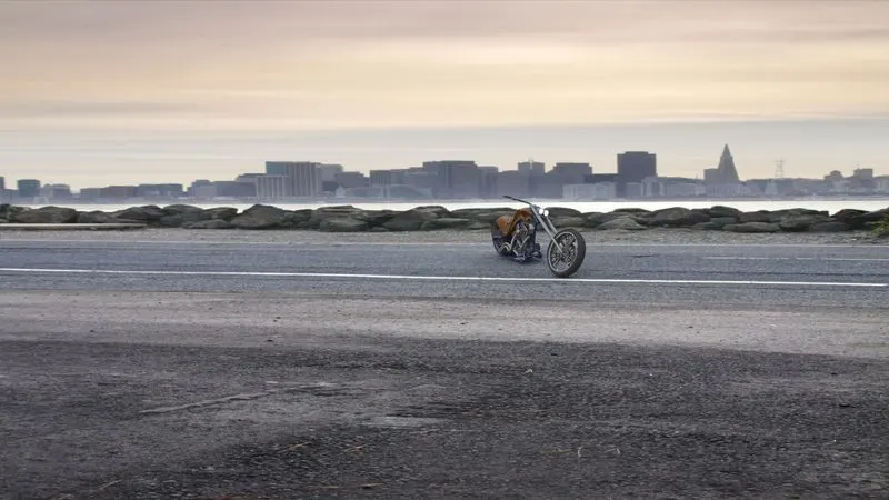
I used bottom-up approach and solid modelling for most of the parts.
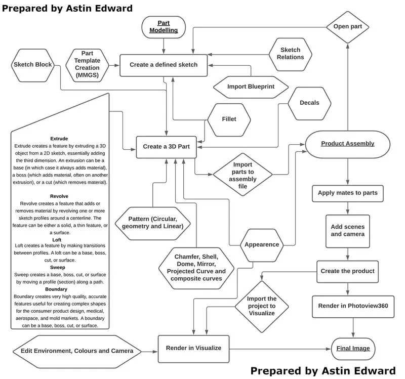
- Creating a defined sketch:
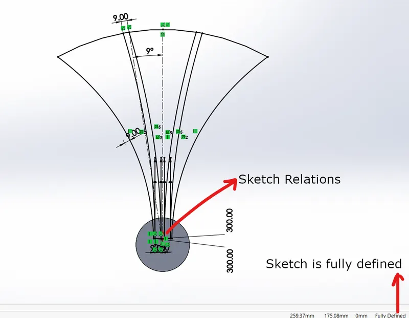
Sketches are initial drawings upon which we model our parts. The above diagram is from the front wheel part I created and it shows how we can define using various realtions and dimension them accordingly.
It is always good to add more sketch relations and less dimension values so that the geometry is flexible for rebuilding with new values.
- Creating parts of Chopper:
- Transmission belt:
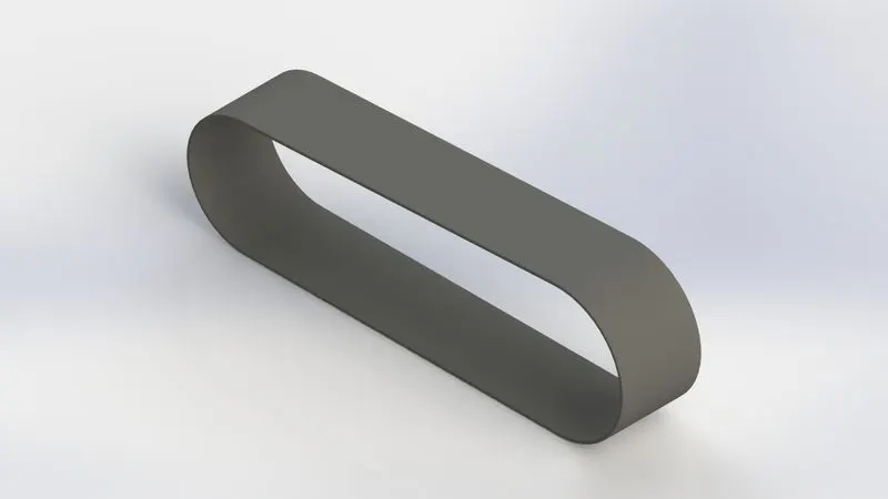
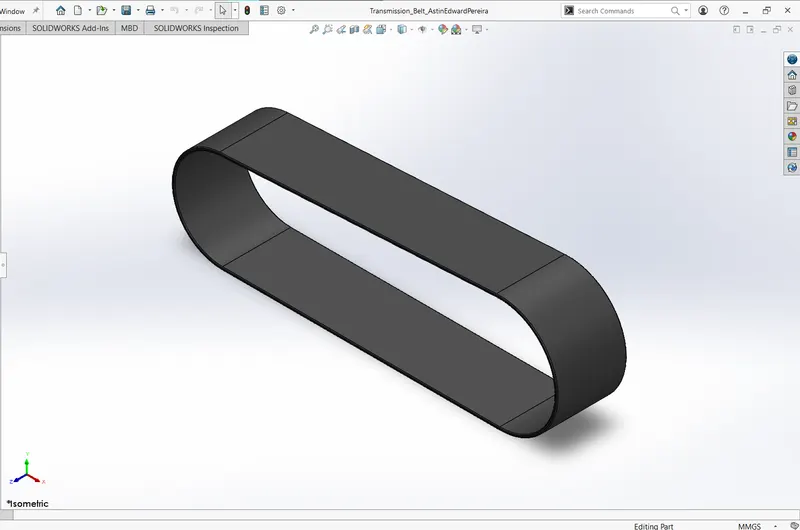
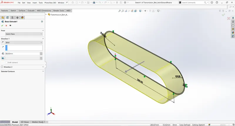
Transmission belt is created by boss extruding from the sketch to 88.00mm(Blind). Finshing the part with a 1mm fillet, which smooths out edges.
- Front Fender:
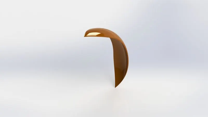
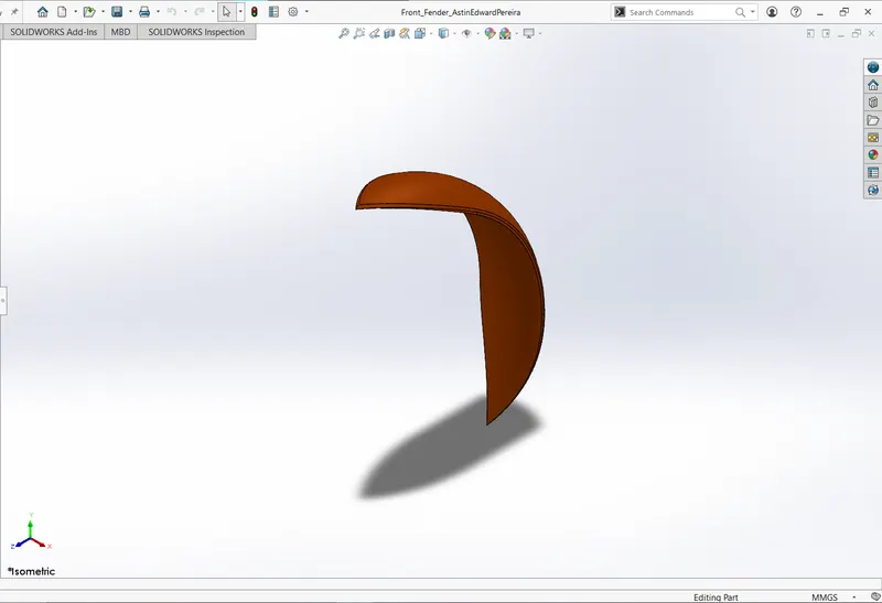
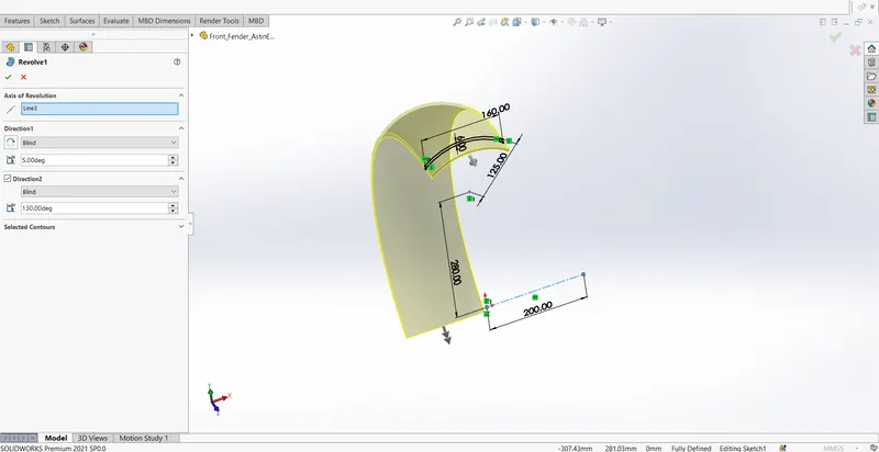
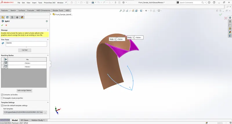
Front fender is created by first revolving our sketch to to certain degree on both direction and then using split tool twice along with its profile sketch to cut out necessary part. Finishing off with appropriate fillet.
- Rear Fender:
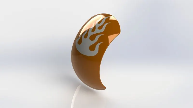
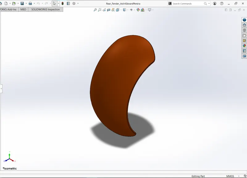
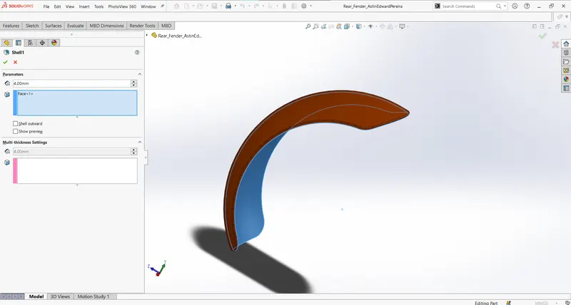
Rear fender is made similar to front fender but uses shell feature to further carve out some material from the part with 4mm thickness.
- Kickstand:
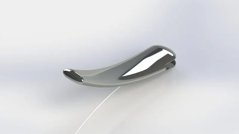
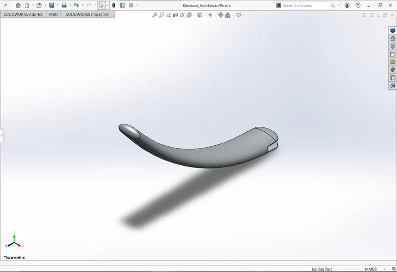
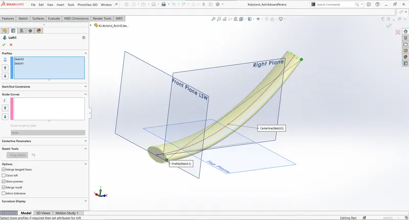
Kickstand is created my lofting between two sketches with appropriate guide curve.
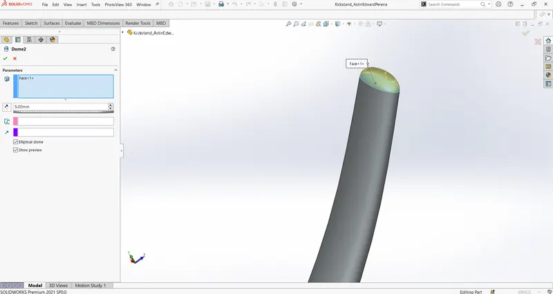
Domes are added to both ends.
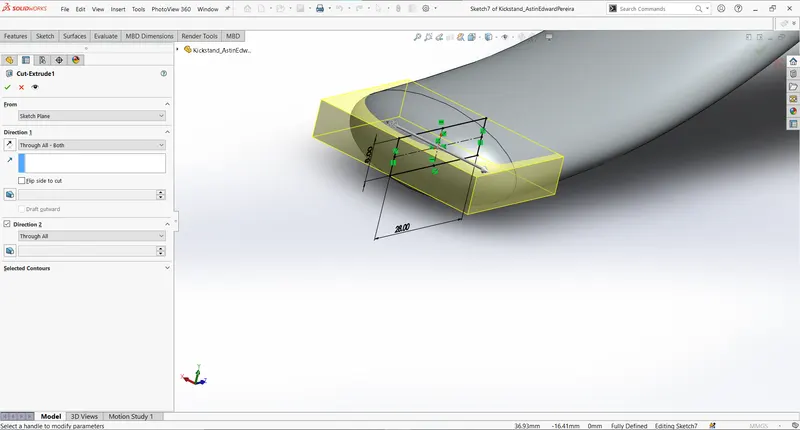
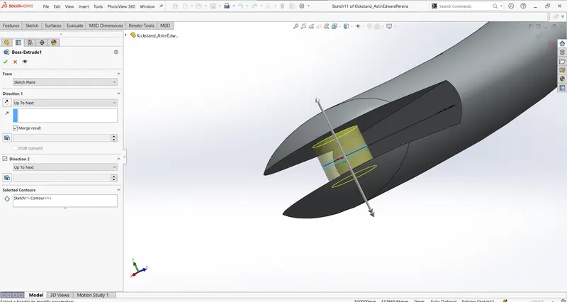
Cut-extrude is used to remove material from one end to accommodate space to connect with the frame, boss extrude is then used to make a connecting pin.
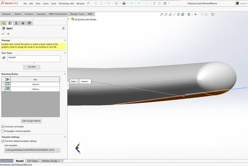
Split tool is used to remove material to flatten the end touching the ground.
- Chain:
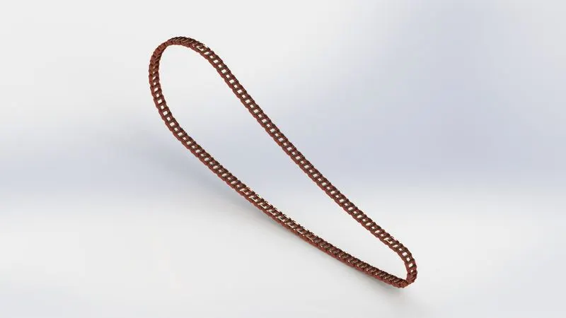
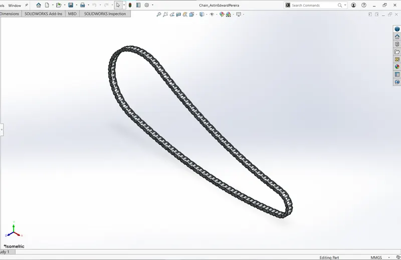
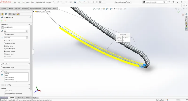
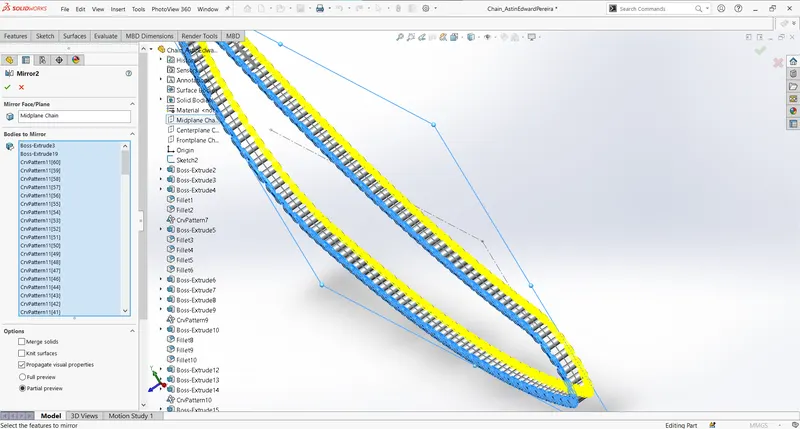
Chain is made using the concept of sketch block, circular pattern, mirror entities along with boss-extrude with offset and different plane parameters.
Initially a profile sketch is created and saved as chain-link 1 and 2 as sketch block, which are used repeatedly to make chain pins and links. For that, a reference a guide sketch is created for the path for chain.
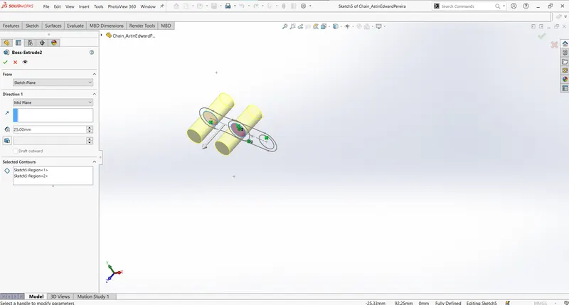
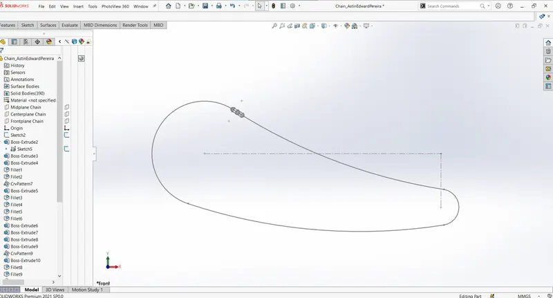
Circular pattern feature is made used to create multiple bodies along the arc, and finally mirror pattern feature is used to mirror the chain links that envelope the pins on the other side.
- Oil Tank:
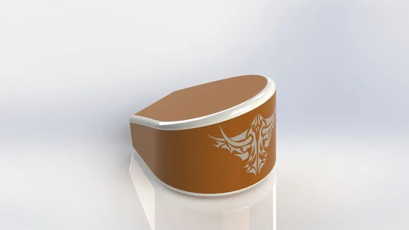
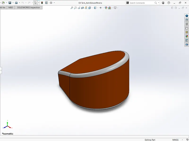
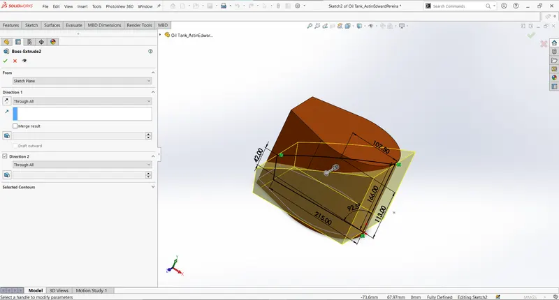
To create oil tank, two boss extrudes from sketches: one on top plane and another on right plane is made.
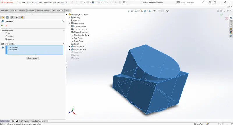
Then by using combine feature, the parts which are common among the extruded bosses are maintained. Other options available in combine feature are add and subtract.
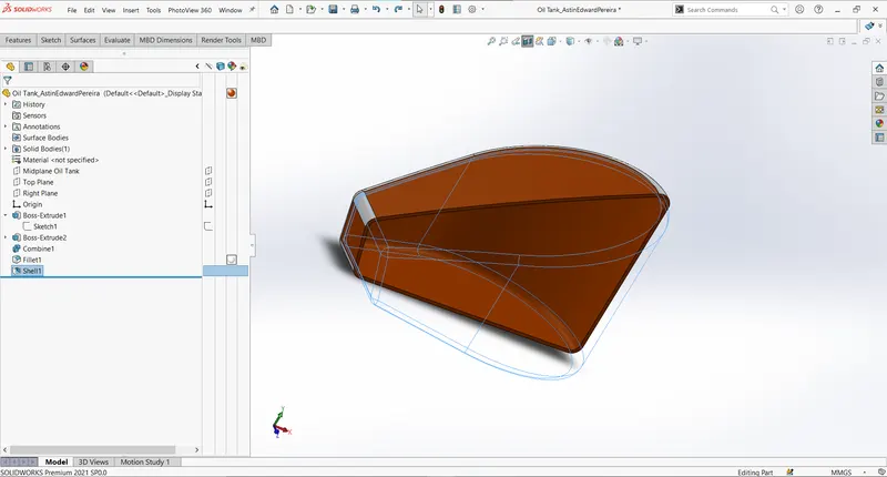
The oil tank is made hollow by using the shell feature.
- Pedal:
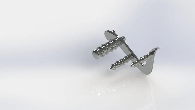
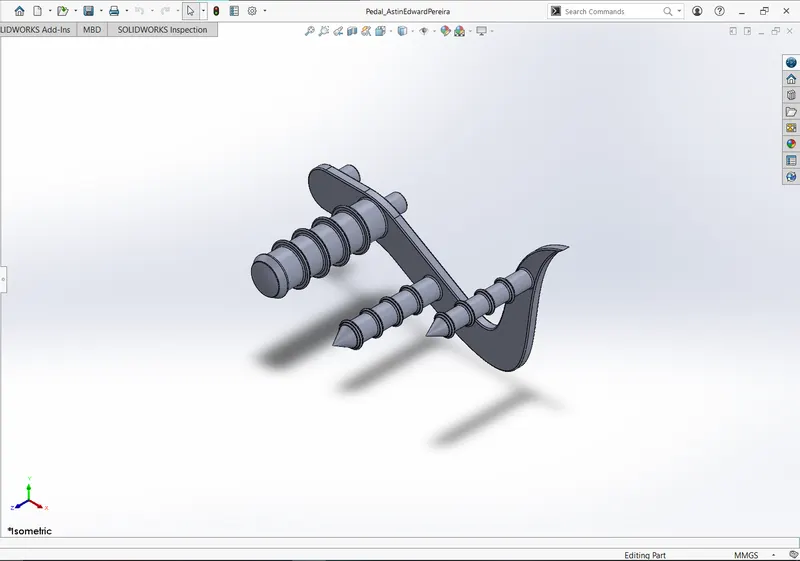
Initial compontes of pedal are extruded from sketches.
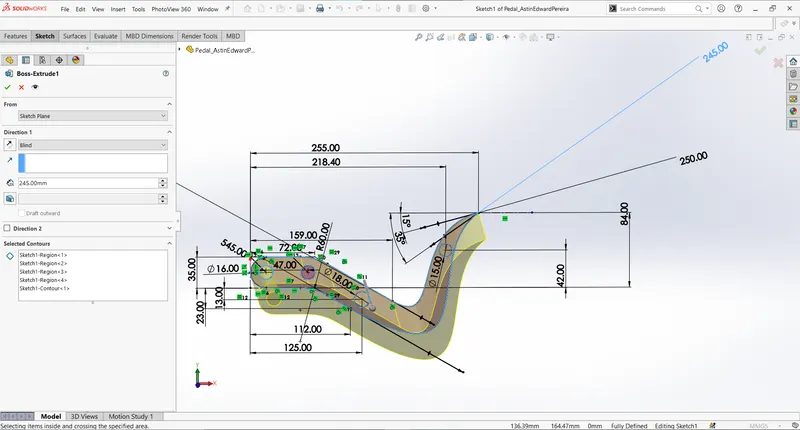
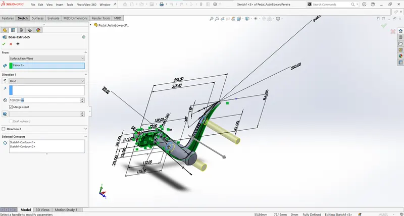
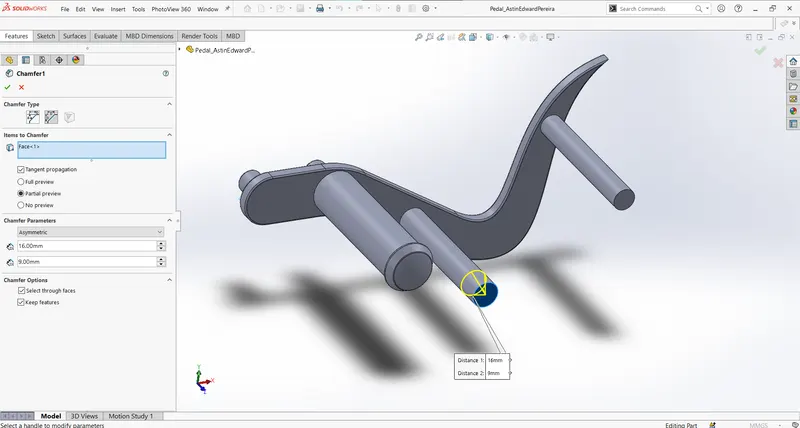
Linear pattern and chamfer feature are used to further modify the part. Revolve feature and filleting are also used whose purpose are explained earlier.
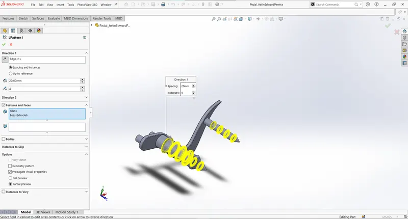
Chamfer type used here is distance to distance.
- Front Wheel
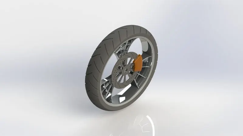
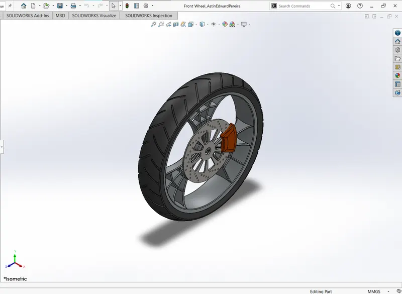
Front Wheel consist of Rim, Tyre, Spokes, Disc and Caliper.
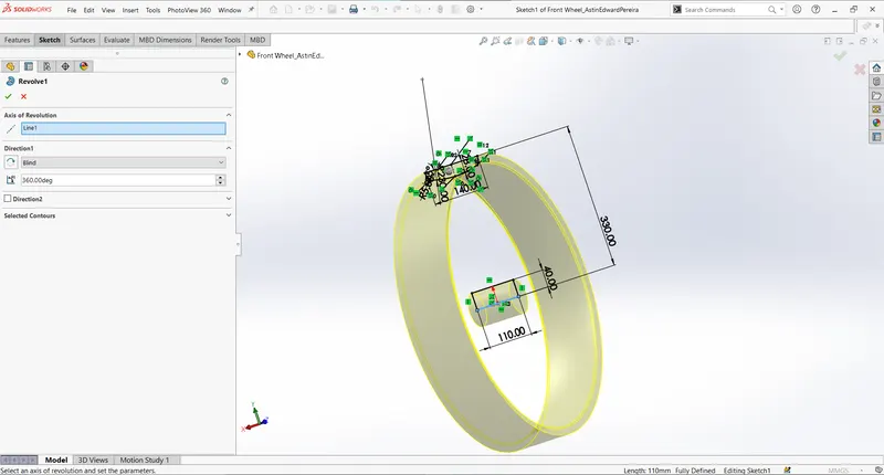
Initially the Rim is modelled using revolve function along with center axle.
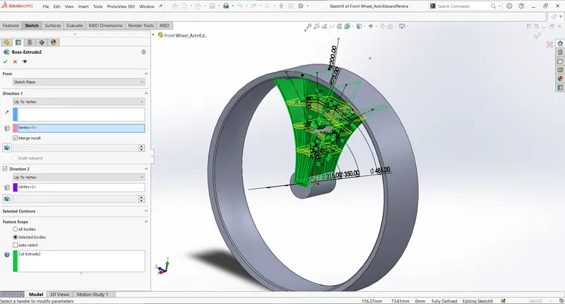
Then for the spoke, first a sketch is created fully defined in right plane and extruded using mid-plane feature. Spokes are made with spider-web design. To create such a design, cut-extrude is done using a profile sketch so that the material is removed in vertical intervals. Then a boss extrude is used to add material horizontally along the profile sketch designed as spider-web arcs. Feature scope is an available option in extrude functions, which make sure about the material or parts that we intend to modify. The direction of the extrusion can be controlled via many formats such as up to next, through all, up to vertex, offset from a plane etc. Each functions comes in handy while dealing with many design specs.
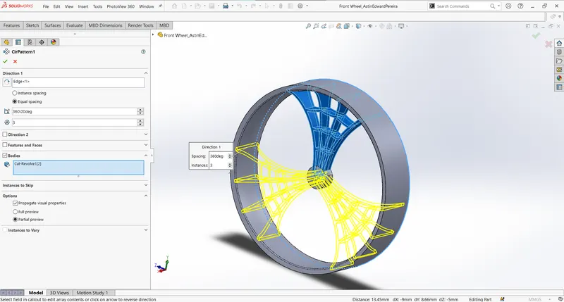
Spider-web designed spokes are then propagated along the rim using the circular pattern feature and SolidWorks provide temporary axes feature with respect to the bodies created, which could be utilized for pattern creation to avoid a construction geometry as reference. I used Rim body's edge as the direction axis for the circular pattern.
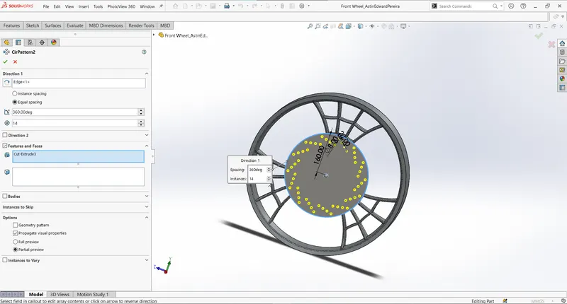
The Rim along with the centre axle and Spokes are combined using add function. Disc is modelled as boss extrude from a circular sketch and holes are extruded on it using another sketches and patterns extensively.
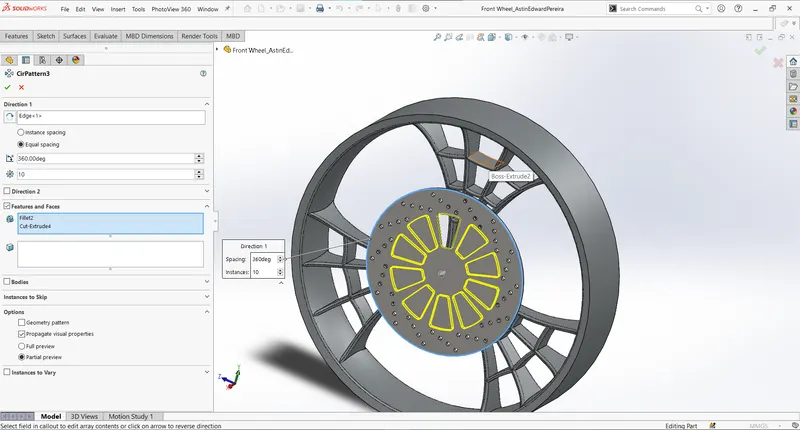
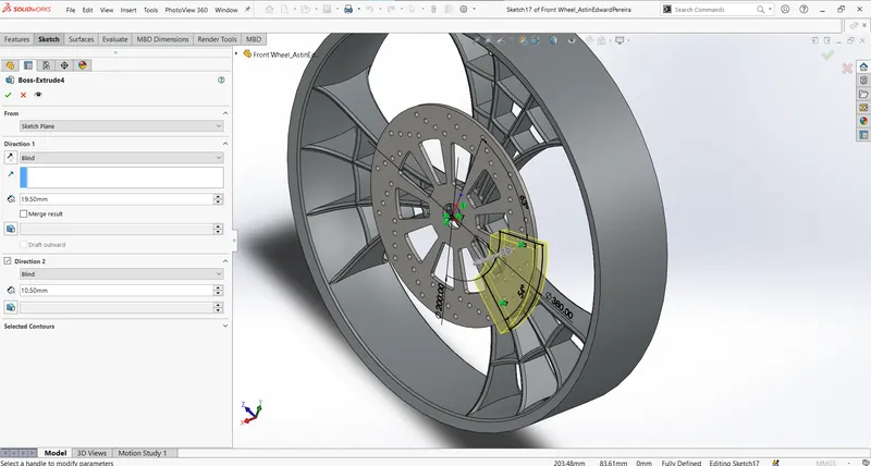
The sketch for caliper is sketched on the surface of disc part created. It is then boss extruded on both direction and later chamfer is added.
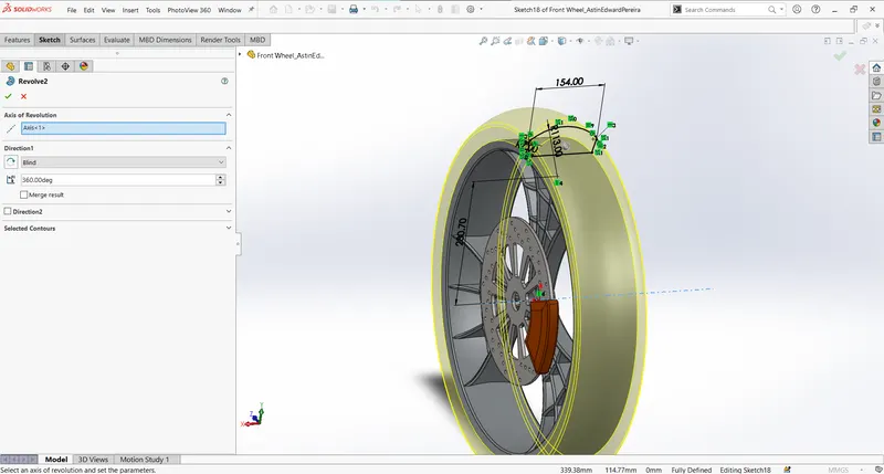
The main material tyre is made similarly as Rim using revolve function and I used temporary axis for the direction of revolve.
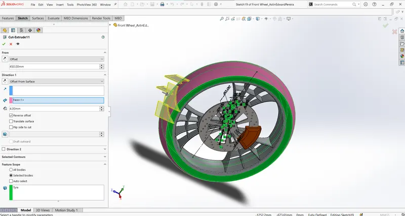
The stripes for the tyre is sketched on the front plane, and offset feature is used to cut-extrude the material off from the tyre surface. The circular pattern feature is then used to propagate the stripes along the whole tyre.
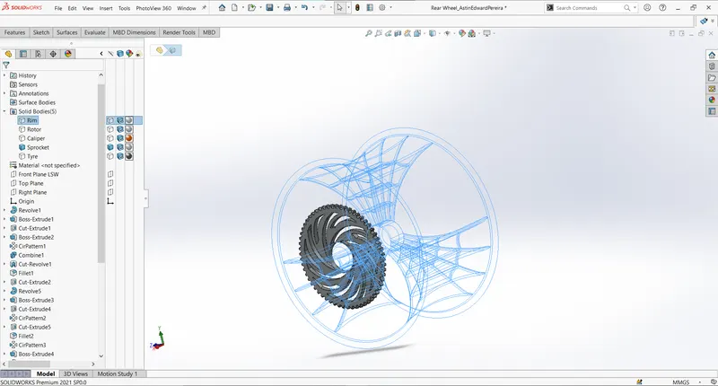
- Rear Wheel
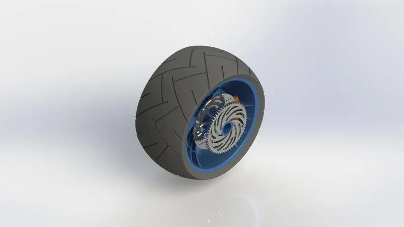
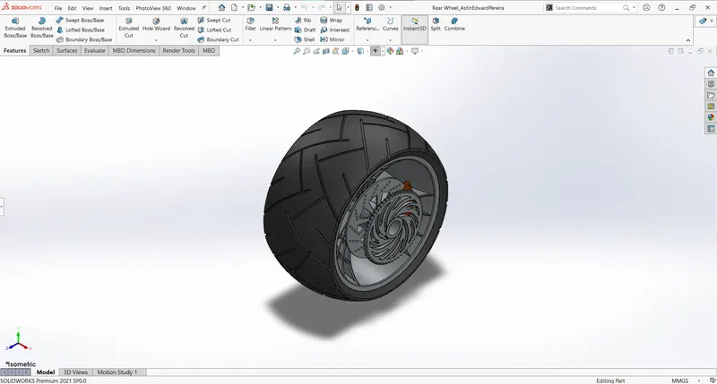
Rear Wheel consist of Tyre, Rim, Sprocket, Disc and Caliper.
Except for the sprocket and minor changes in center axle, the part modelling is similar to that of Front Wheel.
For modelling the sprocket, initially a fully defined sketch is boss extruded and its circular ends are chamfered off. Then a extruded cut is made on the end by carefully selecting sprocket as the only material via feature scope option.
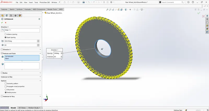
Further cut outs are made on the sprocket using extruded cut and circular patterning it.
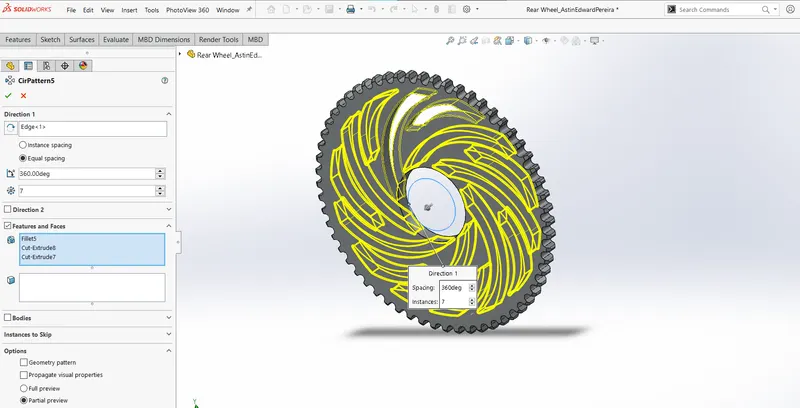
The part is finished by adding necessary fillet.
- Front Fork:
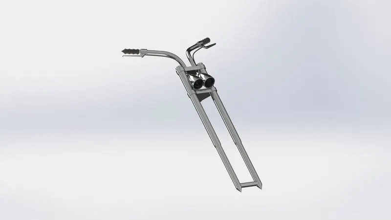
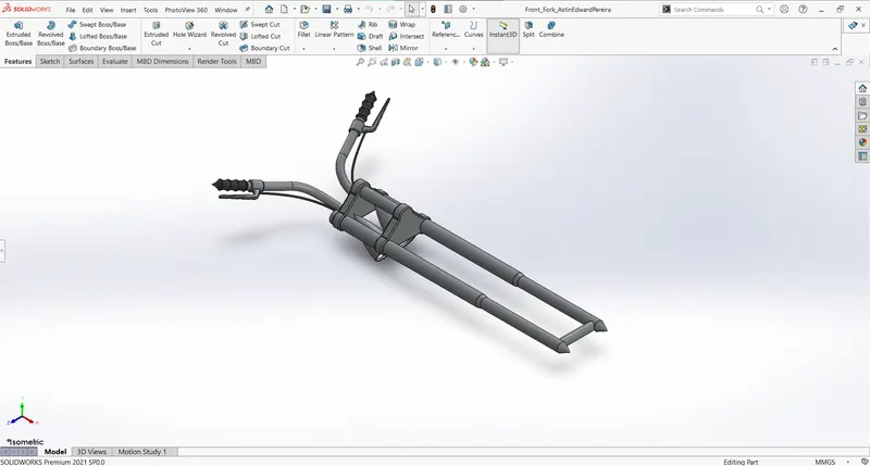
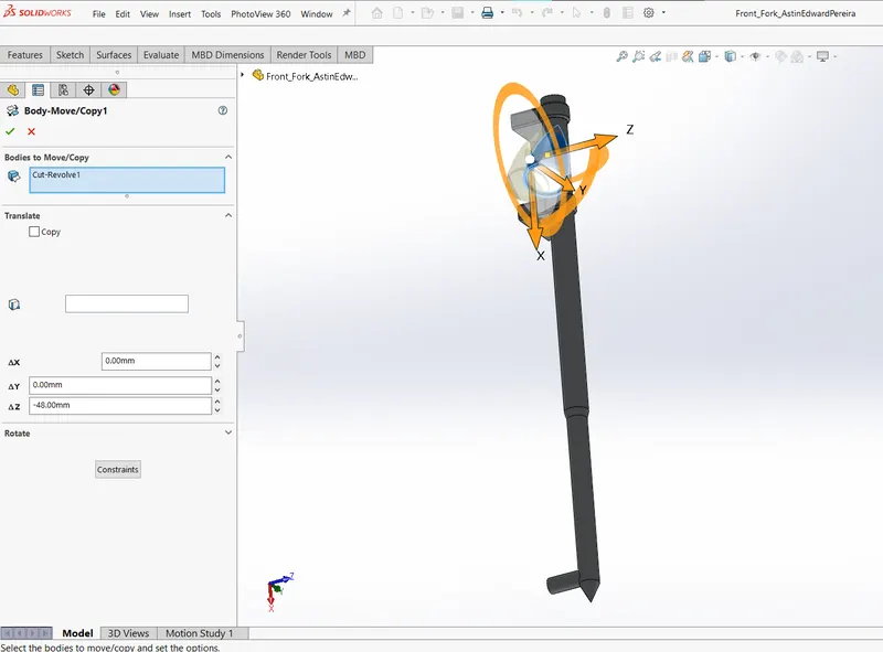
Front fork is part modelled also using the features explained in the previous parts such as revolve, boss-extrude, dome, fillet, combine, mirror etc. except some are completely new like, moving and copying body. Which is used here to re-align the position of headlight.
This feature is used to move the positon of a body in space by changing the value of x,y,z axes parameters.
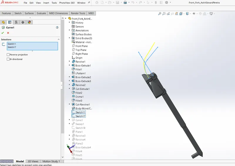
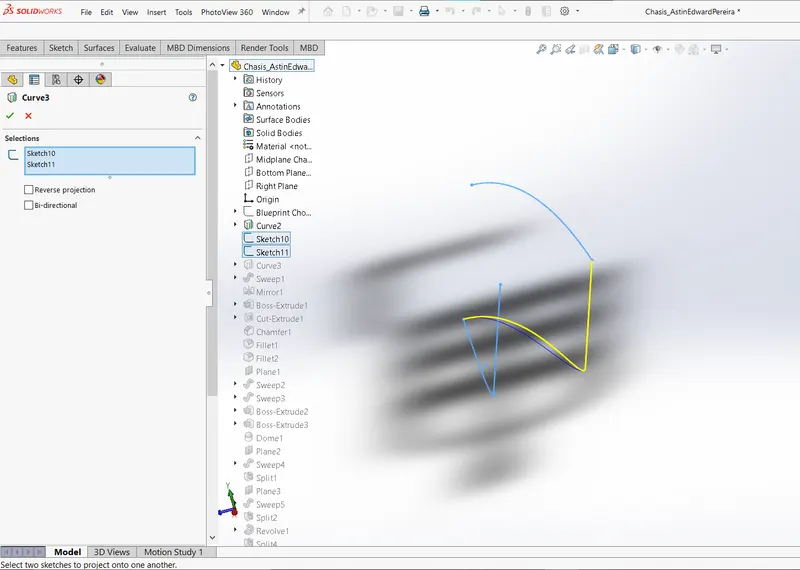
The handle of the front fork is part modelled using the feature known as projected curves which utilizes two 2D curves on perpendicular planes and project them to a 3D curve. Here two curves one in top plane and other on front plane is selected to create a projected curve on the space (Yellow curve).
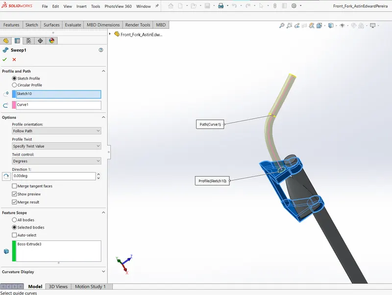
The projected curve is made used as the path for the sweep funtion to form the handle for the fork.
- Chassis:
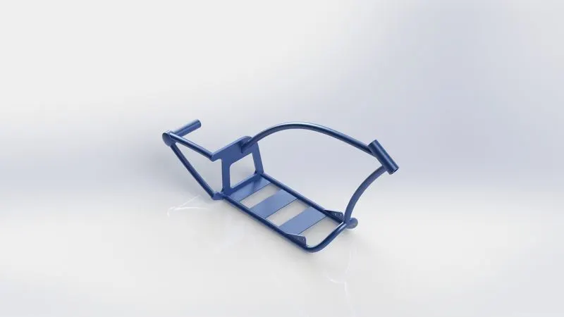
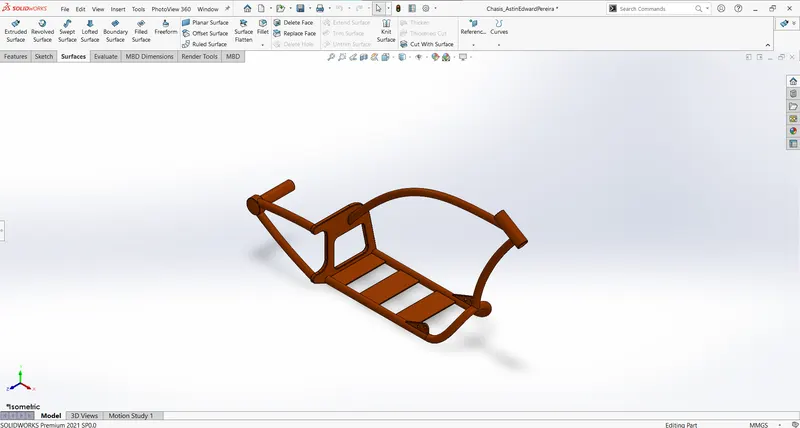
Chassis is also made using the techniques already mentioned; Boss-extrude, sweep function, cut-extrude, chamfer, dome, mirror, fillet, combine. It further utilizes blueprint as the sketch picture for a good reference.
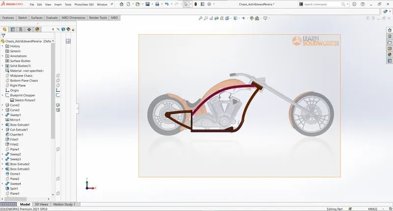
It also uses the concept of projected curves for creating path for the chassis elements to form by sweeping.
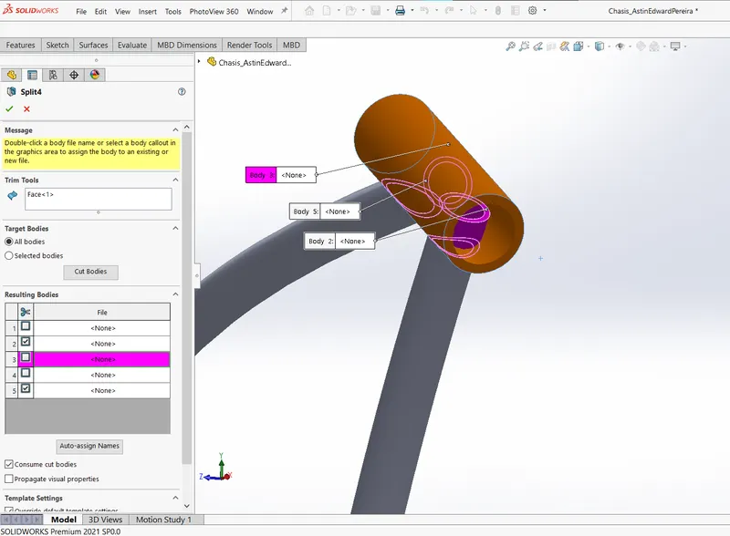
Another example of split tool could be seen in chassis where some of the material inside the fork holder is removed by selecting the inside face as the trim tool profile.
- Engine:
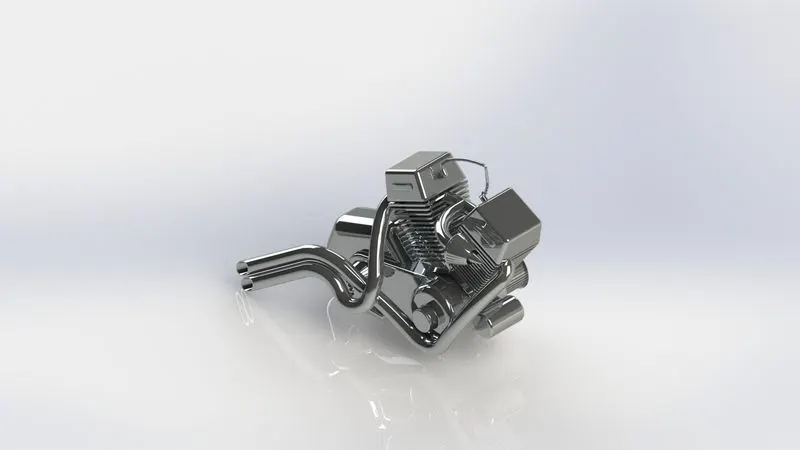
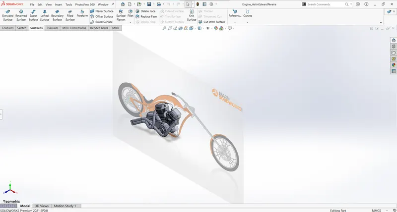
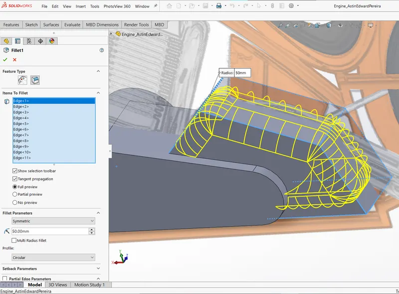
Engine is a complex model which utilizes most of the features of solid modelling to create. In the below example, it can be seen that how fillet is used to alter the geometry and shape of the casing effectively.
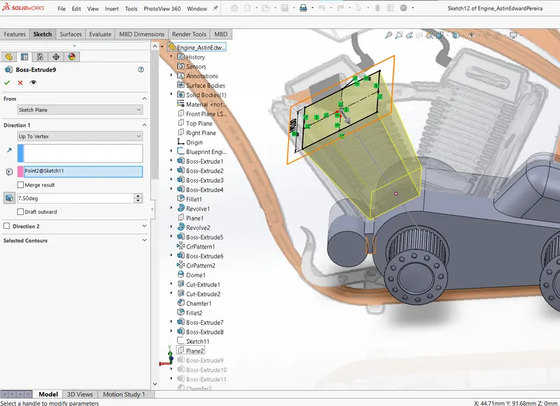
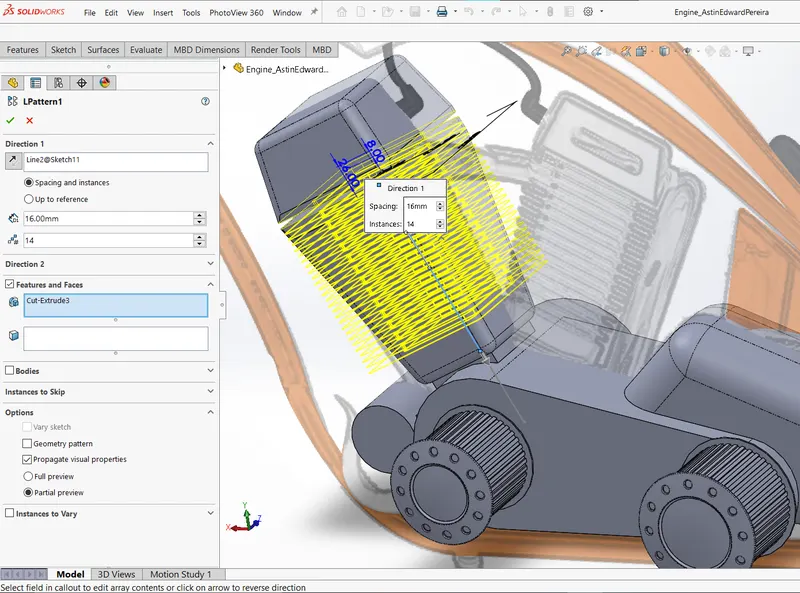
SolidWorks primarily has 3 planes, but that doesn't mean we are limited to sketching or modelling to that planes alone. We can create as many planes we want for our construction. The cylinder is made from such a plane. And then linear pattern of cut-extrude is propagated for fins.
The single cylinder is then mirrored to form twin cylinder model for the engine.
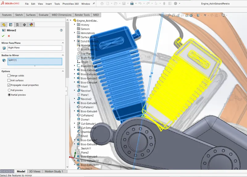
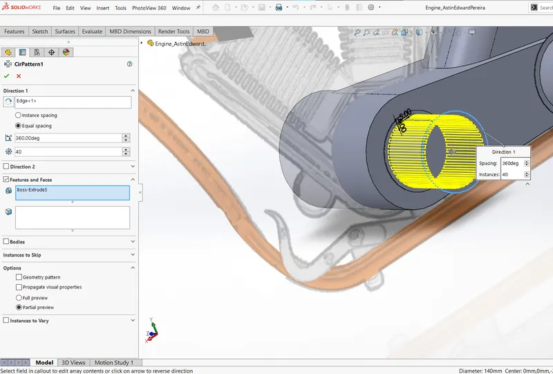
Transmission gears and casings are modelled using extrusion, revolving and applying dome, fillet, pattern etc.
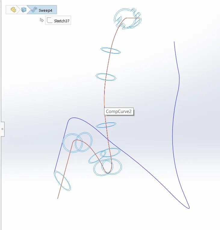
The exhaust manifold uses projection curves as well as composite curves for the path to sweep for.
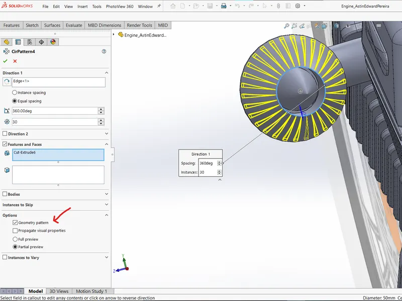
There are both advantages and disadvantages when merging solid bodies, it is always preferred to merge the bodies last so that we can treat them individually. However, we can utilize the tool specifications to nullify the disadvantages of merging solid bodies or even single body with no regular geometry. For example, while applying pattern the tool considers the whole body to propagate the feature. But utilizing the geometry pattern option, I can avoid propagating the cut-extrusion to pipes and cylinders because air filter and engine are merged.
- Gas Tank:
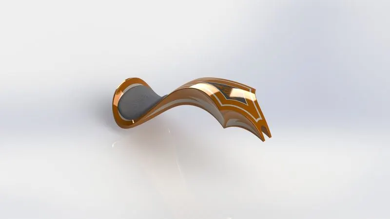
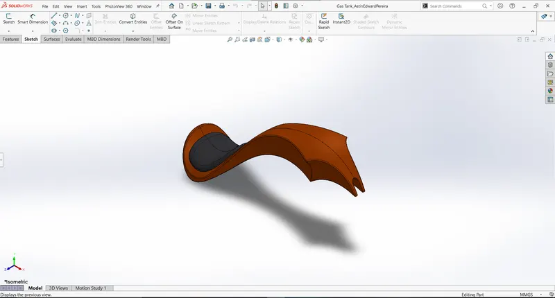
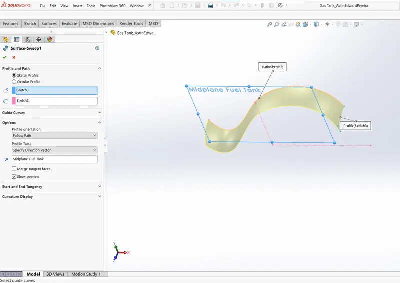
Gas tank is modelled different from the rest of the parts. It extensively uses surface modelling tools. Surface tools are good to use with bodies having lot of curves. First of all, surface sweep is used to create the top surface of the tank.
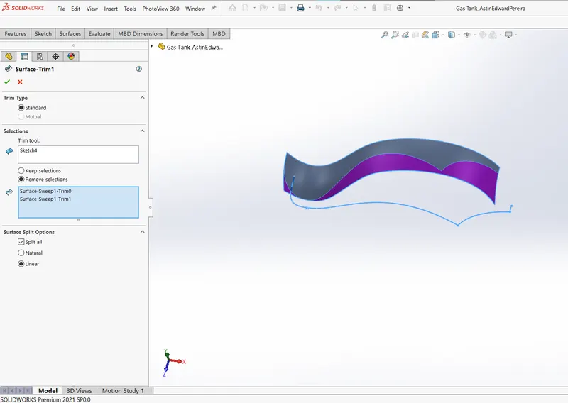
The created surface is trimmed using appropriate profile sketch to get intended design of the gas tank.
Moving to the side, front surface of the tank is modelled using loft feature which creates a triangular curved surface.
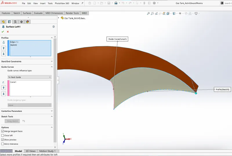
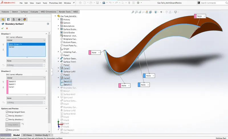
Rest of the side surface is created using boundary feature, where boundary parameters are sorted into 2 directions where the curve profile is used to cover up and make the surface.
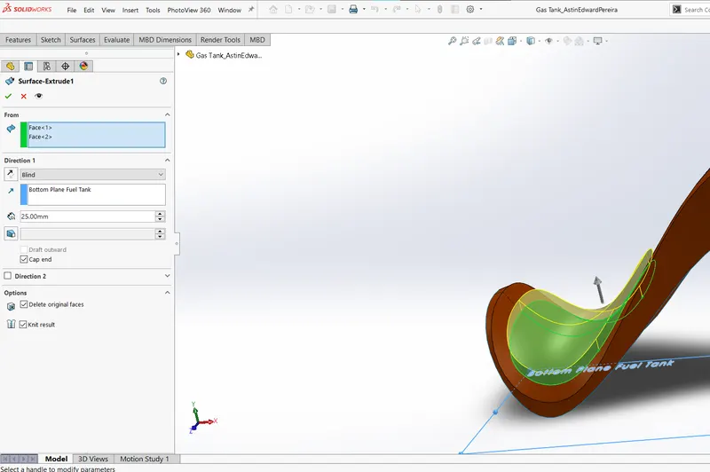
Similar to boss extrusion, surface extrusion is used to create seat on top of gas tank.
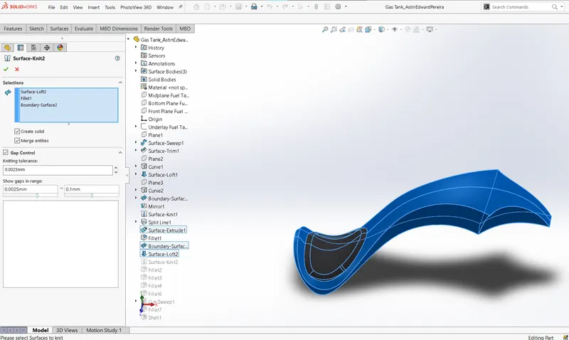
Finally mirroring is done to form the complete gas tank and knit feature is used to combine the surfaces into a solid body. Fillet and shell is used to finish off the part modelling.
- Product Assembly:
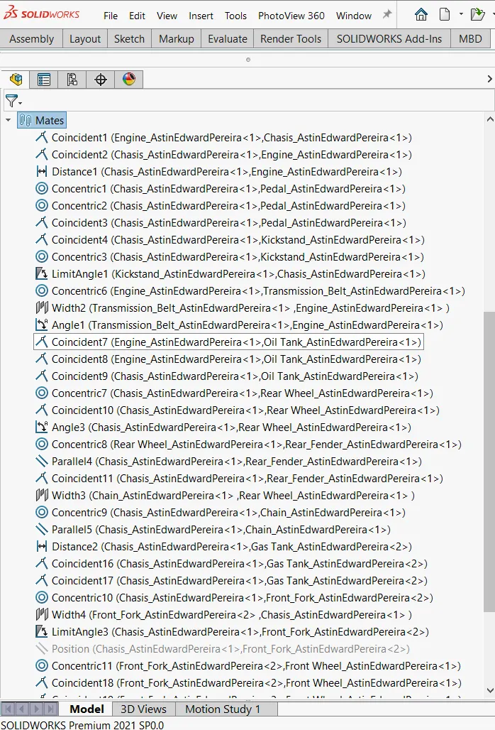
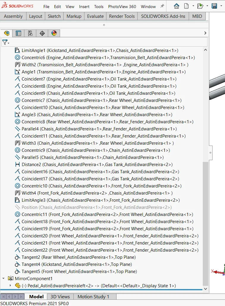
The part files are imported and assembled in assembly file. Chassis is fixed at the origin of assembly space and rest of the parts are mated using with reference to planes of chassis and with parts of adjacent motion. Float option can be used to check if the mates are working properly as a whole product.
Mates are the feature that what holds the parts of the product together and makes the assembly possible.
- Standard Mates:
Standard mates include angle, coincident, concentric, distance, lock, parallel, perpendicular, and tangent mates.
- Advanced Mates
Advanced mates include limit, linear/linear coupler, path, symmetry, and width mates.
Mates used:
1.
2.
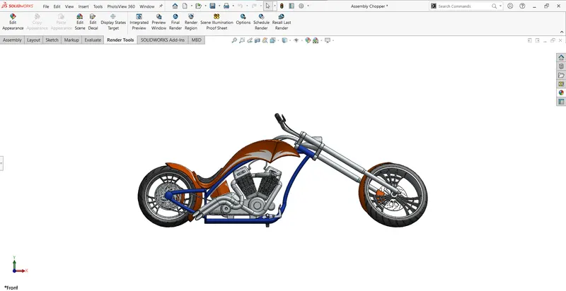
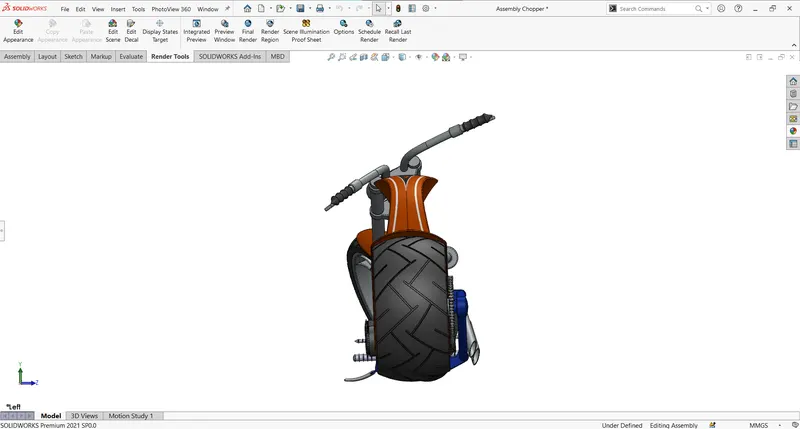
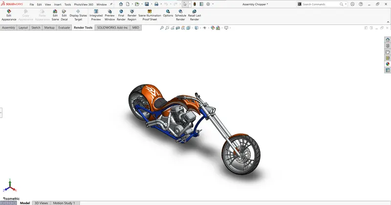
Apperences of the parts can be edited while part modelling or inside the assembly file. Appearences and colours and be further edited in Visualize when the product is rendered using it.
Frontview:
Sideview:
Isometricview:
- Render in Photoview360:
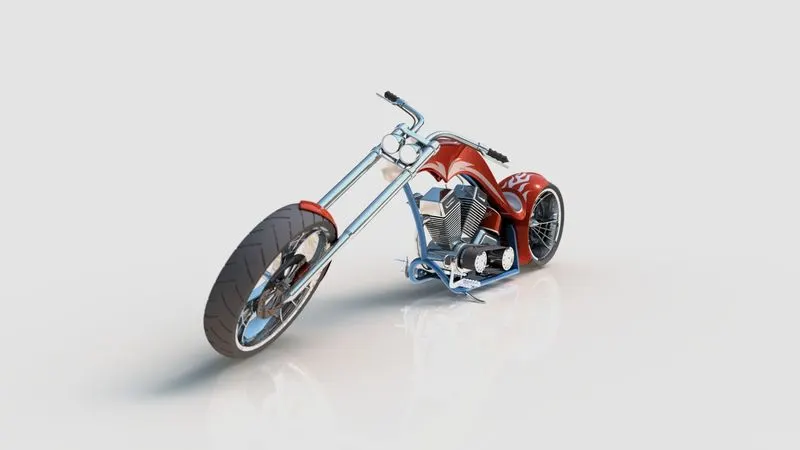
1.Camera view:
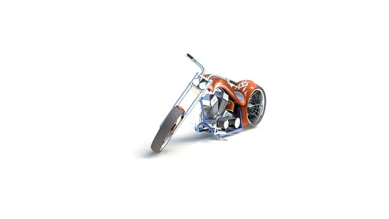
2.Isometric view:
3.Front view:
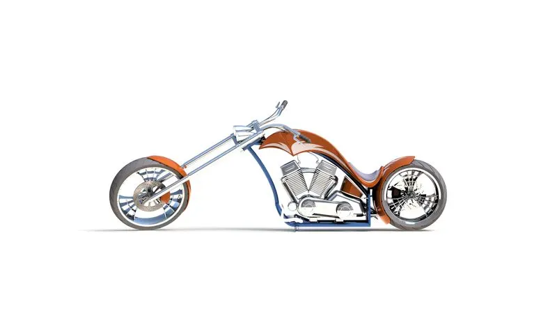
4.Side view:
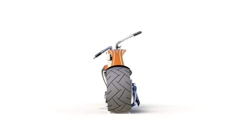
5.Top view:
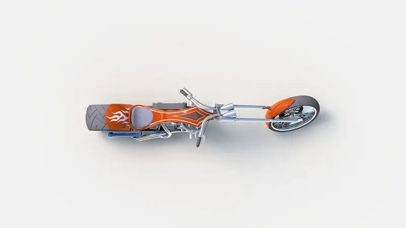
6.View with background scene:
- Render in Visualize:
1.HDR Environment Route66(a):
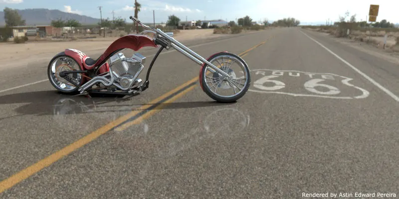
2.HDR Environment Route66(b):
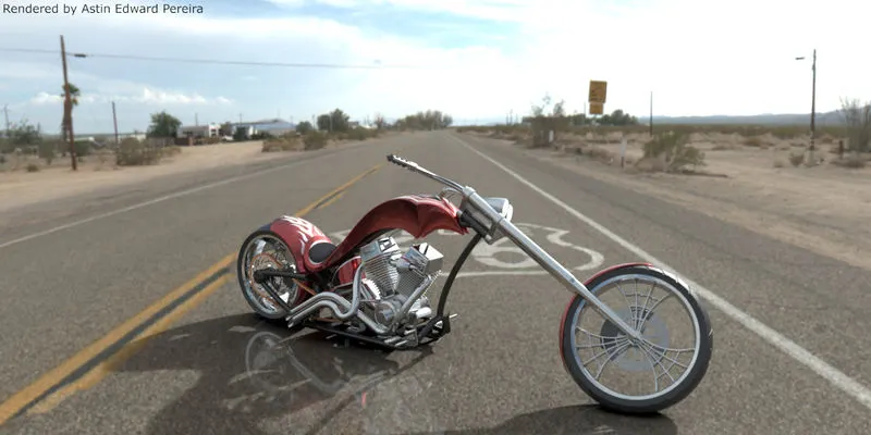
3.HDR Environment Route66(c):
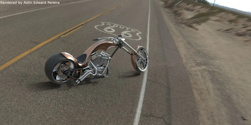
4.HDR Environment Sunny Driveway:
- Conclusion:
SolidWorks is a effective 3D modelling tool and with the right techniques and sufficient planning one can easily model the parts and assemble them in order to present or prototype a design.
The model I used briefly covers majority of the tools in SolidWorks and important tools are worked out thoroughly while designing. While designing a product, one must start with the end result in mind. I have to accommodate for the client's flexibility and post processing of the product while designing. Use geometrical relations and parts' mates that works best and requires minimal updating of numerical values. Through this project I have been able to successfully design a cosmetic model of the American chopper and was able acquire skills to model and render a product in SolidWorks and Visualize.
- Acknowledgement:
I would like to thank my support engineer and mentor Meka Mahendranath Chowdary for guiding me through this project.
I also find Jan-Willem Zuyderduyn's solidworks course provided for me by Skill-Lync extremely useful for the completion of the project.
Reference Links: OCC_Source Dassault Systemes WikiSource Guide Cliff Vaughs
Software Tools used: SolidWorks2021, SW Visualize, GIMP, LucidChart.