Modelling of Sunseeker Predator 108 Yacht - SolidWorks, Visualize.
Report on modelling and rendering of Sunseeker Predator 108 Yacht
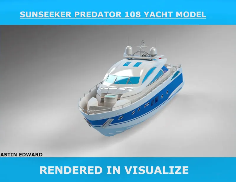
INTRODUCTION:
Sunseeker International is a British luxury performance motor yacht brand. Originally named Poole Power Boats, the company was founded by brothers Robert and John Braithwaite in 1969. The company changed its name to Sunseeker International in 1985 and has since become a global icon. - Wikipedia
Sunseeker Predator 108 is a 32.92 m luxury motor yacht. The yacht has a beam of 6.3 m and a draft of 1.58 m, with a fiberglass hull. It is powered by MTU engines; V16 2000 of 2000 HP totaling at 6000 HP giving it a maximum speed of 45 knots and a cruising speed of 35 knots. The motor yacht can accommodate guests in 4 cabins with an interior design by Sunseeker. The motor yacht CASINO ROYALE is a Sunseeker Predator 108 built in 2004 with 4 cabins for 8 guests. It featured in the James Bond movie by the same name. - Casino Royale
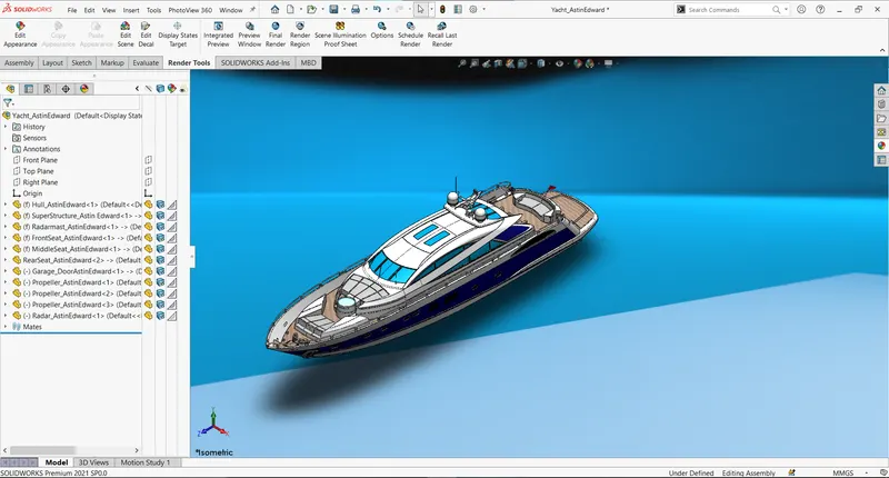
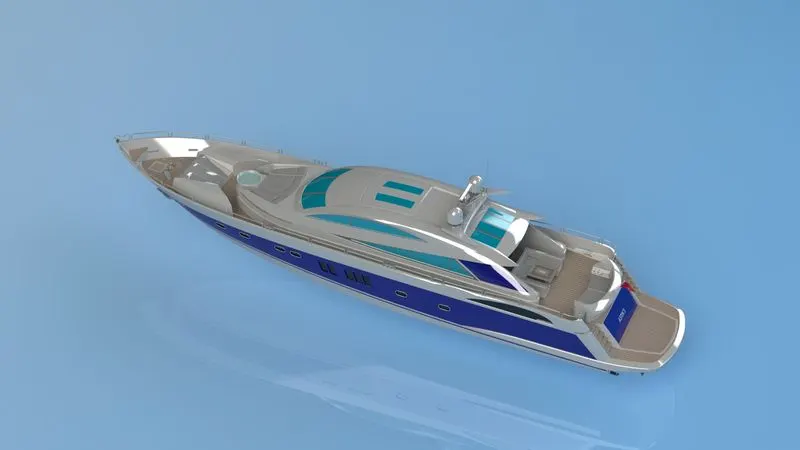
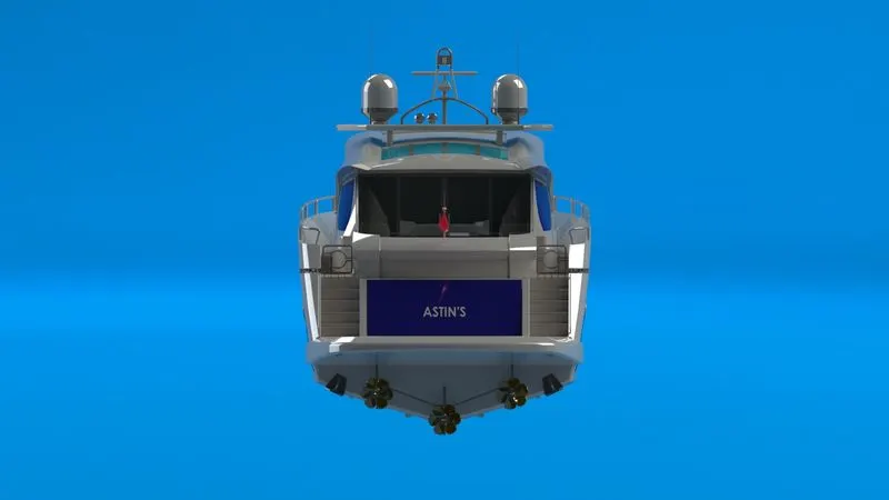
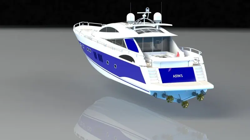
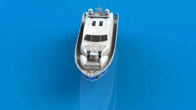
The project deals with the modelling and rendering of this product using SolidWorks.
The yacht model is a very good visualisation to explore the advantages of surface modelling and how it has an edge over solid modelling with products having more curvy designs.
OBJECTIVE:
In this project a 3D model of Sunseeker Predator 108 Yacht is created using Solidworks and rendered using Photoview360 and Visualize.
DESIGN APPROACH:
Bottom up approach, i.e. parts are created individually and are inserted in assembly later and surface modelling tools were mostly used in part creation, where in chopper design project solid modelling tools were given focus.
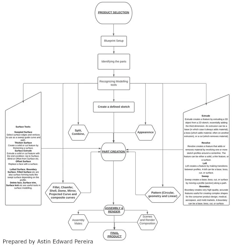
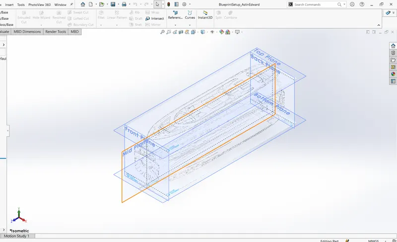
The Yacht model consists of 9 parts, each one of them modelled using a base reference part which is the blueprint setup.
THE NINE PARTS AND SOME OF THE TOOLS WHICH USED ARE:
1.PROPELLER
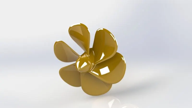
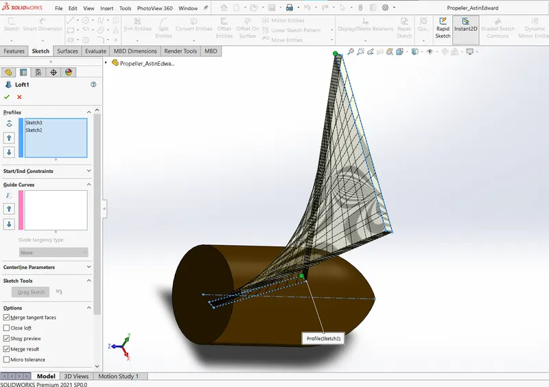
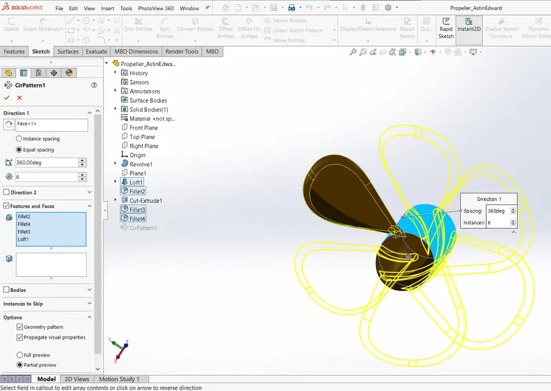
The propeller is modelled using revolve for the axis component and circular patterning one of the leaf created using loft.
2.RADAR
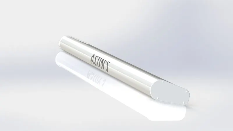
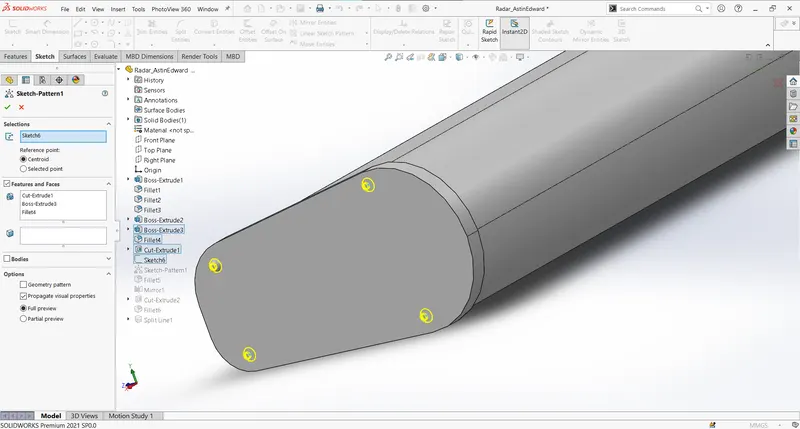
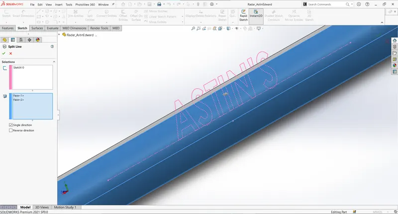
The radar is boss extruded from the mid-plane so as to mirror the solid after modelling. Some of the features worth mentioning is the use of points in sketch which utilized for sketch driven pattern and use of split feature to project text on the surface of the radar.
3.HULL
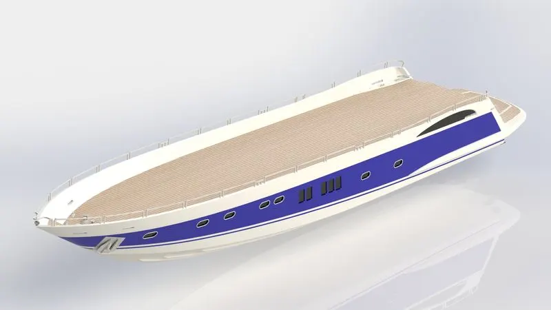
The hull is the most important part in the yacht design. Several tools both solid and surface techniques are used to model the hull.
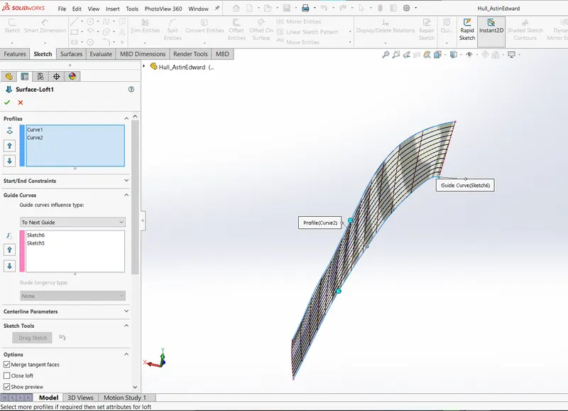
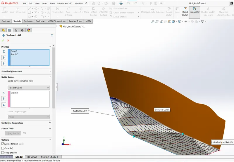
Initially two surface lofts are used to create the outer most surface edges of the hull.
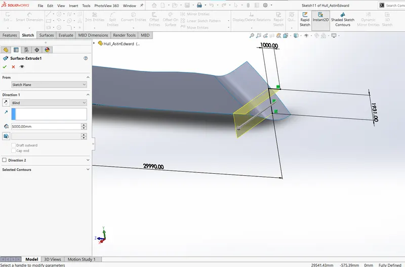
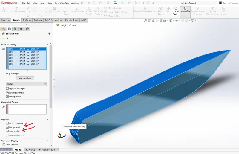
Further surfaces are made and "fill surface" tool is used to close the surfaces to create the first solid body while modelling the hull. If gaps are present, this will lead to failure.
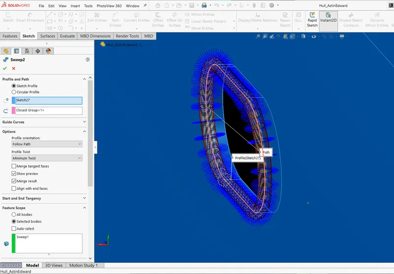
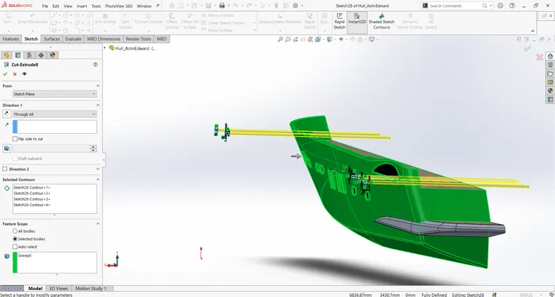
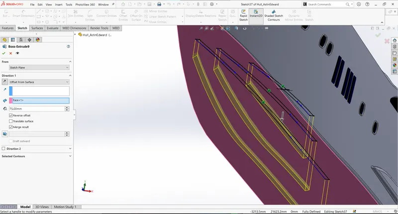
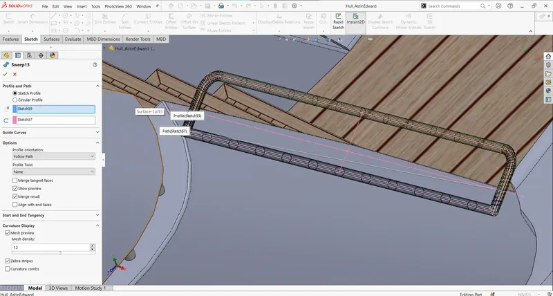
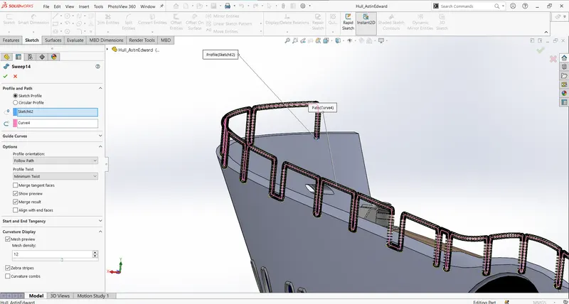
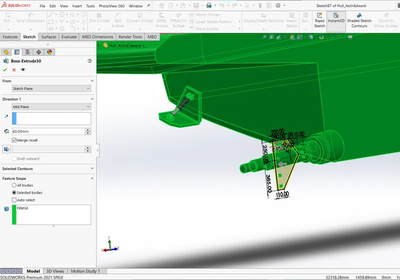
The "swept surface" is used to create window edges, stair-way handlebar and cut-extrude and boss-extrude features are also used to further detail the created solid body.
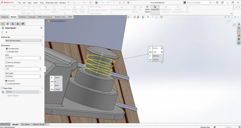
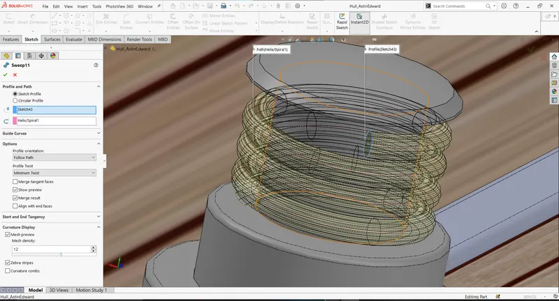
A combination of helical sketch feature and swept-boss feature is used to create the cable. Deck surface and stairs' appearance are changed using decals.
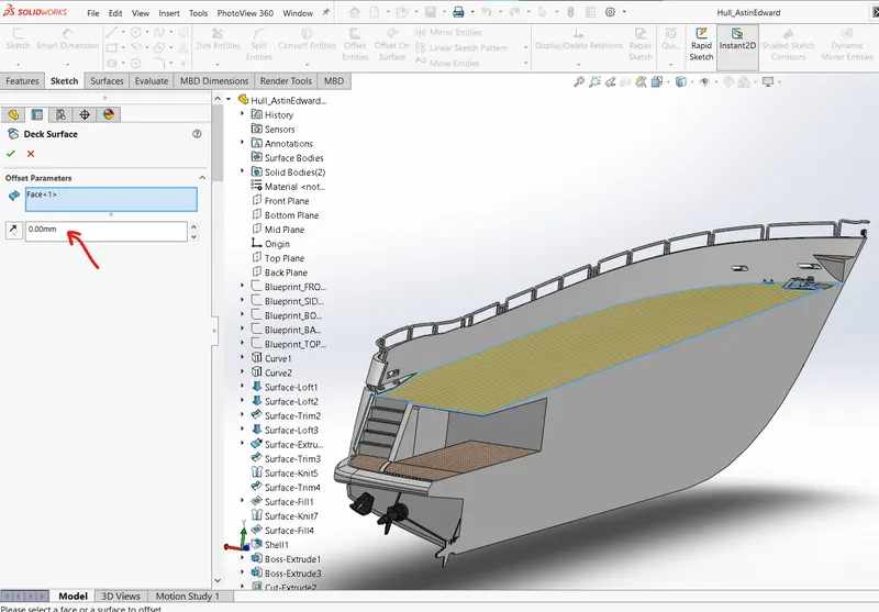
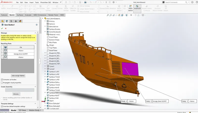
While modelling the hull, it is also helpful to create surface offset that will act as reference geometry for the rest the parts that come up at the top of the deck. The garage door component is also made from splitting the hull while modelling.
4.GARAGE DOOR
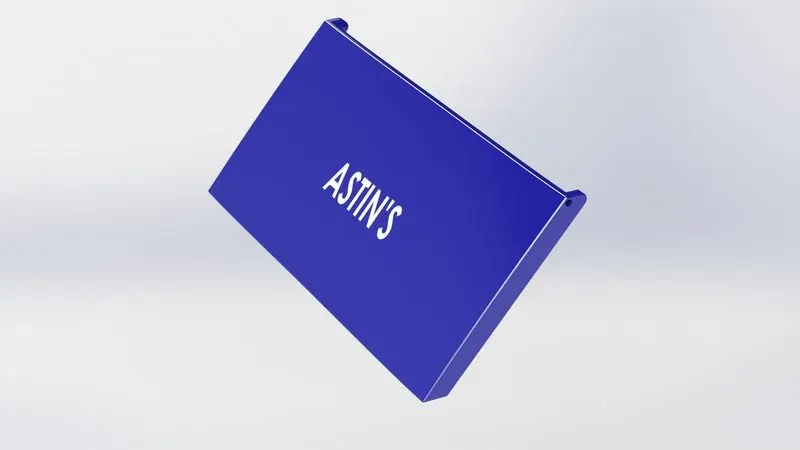
The garage door raw body is taken from hull.
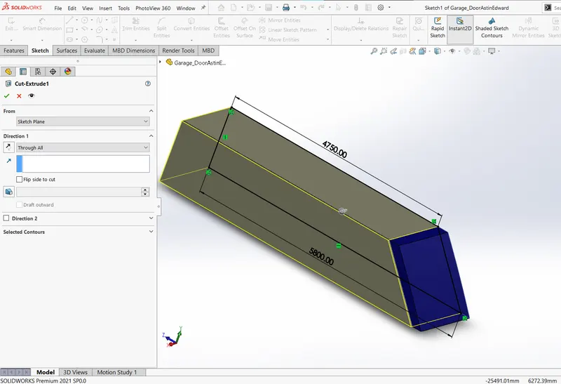
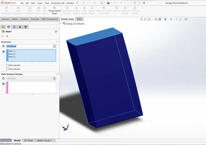
Cut extrude and shell feature is used to modify the solid body to create intended shape.
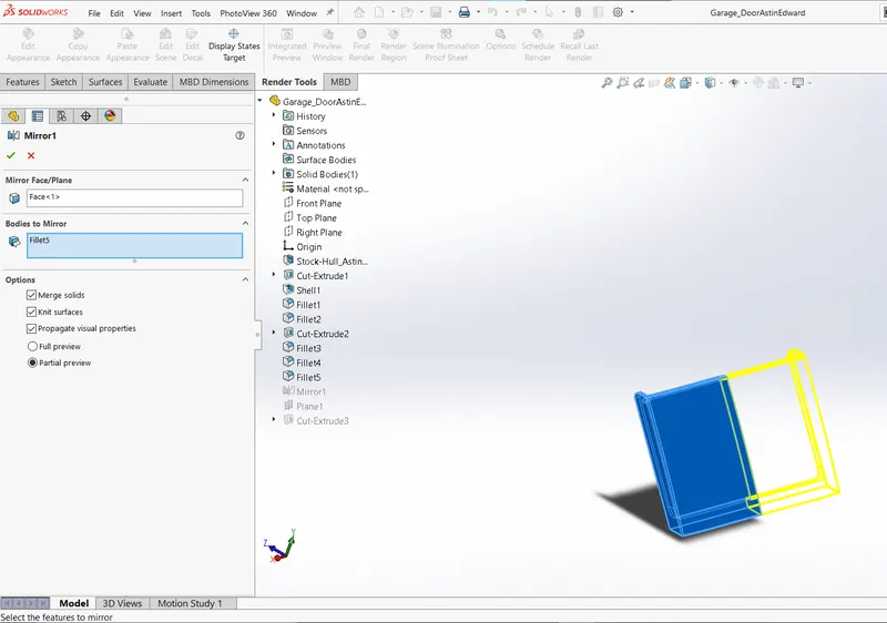
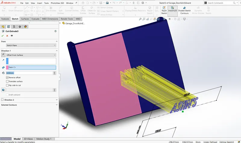
The part is mirrored to create the garage door after necessary filleting and editing. Here text in sketch is used to create extruded cut where in radar it was used to project on the surface.
5.FRONT SEAT
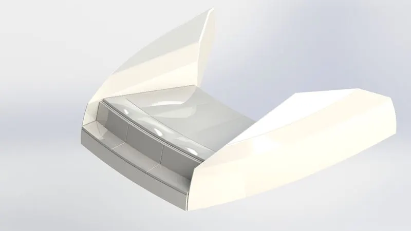
The front seat is also designed using the symmetrical approach and the part is mirrored at end to get the desired result.
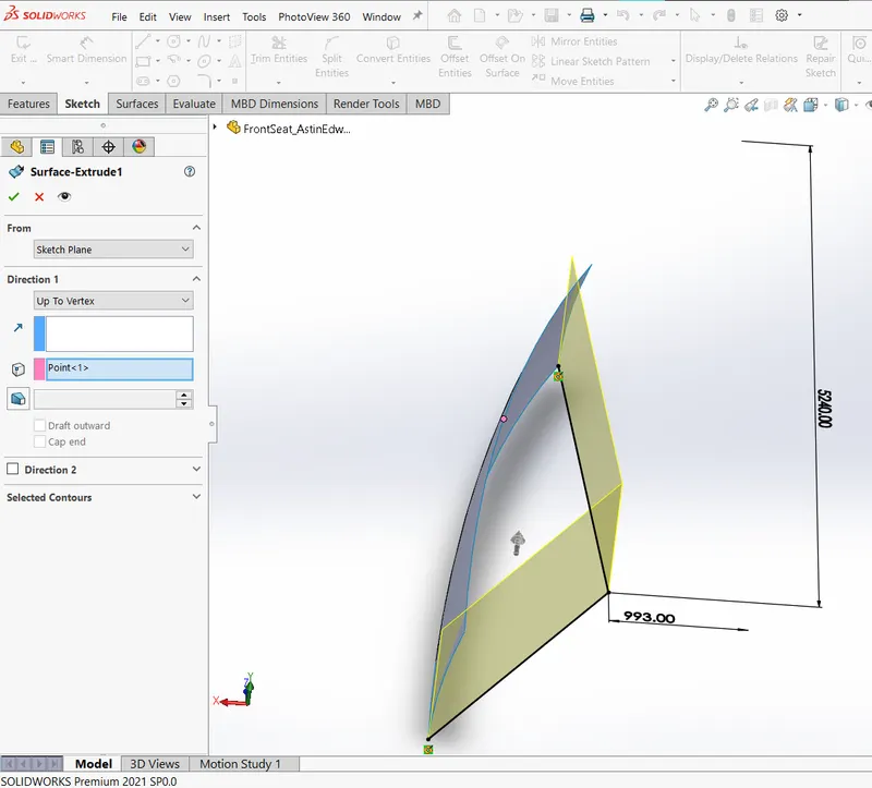
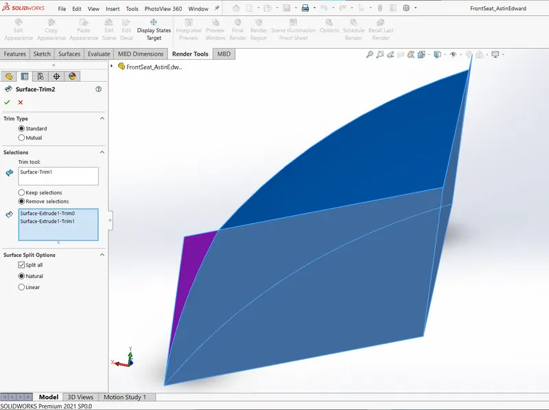
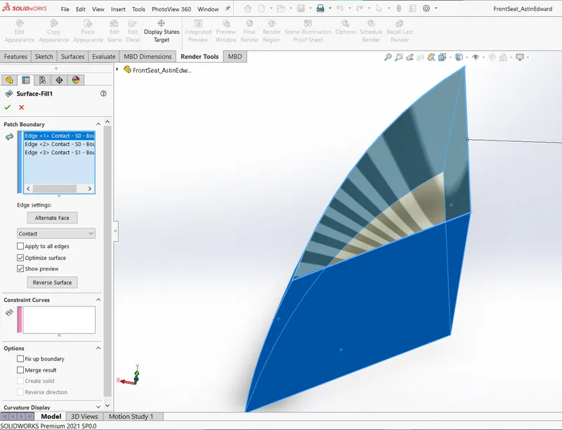
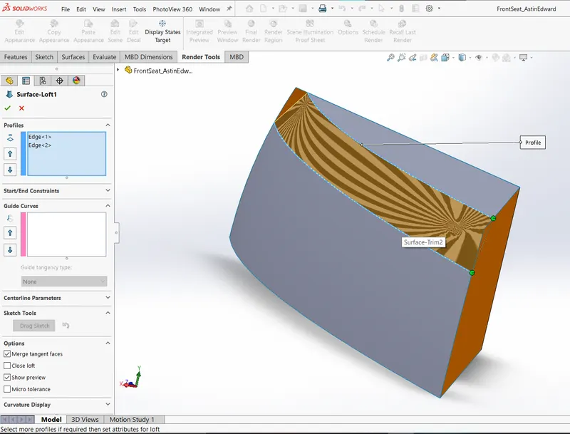
The structures are first surfaced using loft, sweep, extrude, fill and knitted to form solid after necessary trimming.
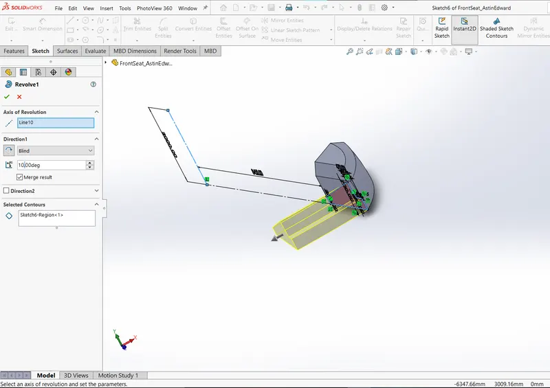
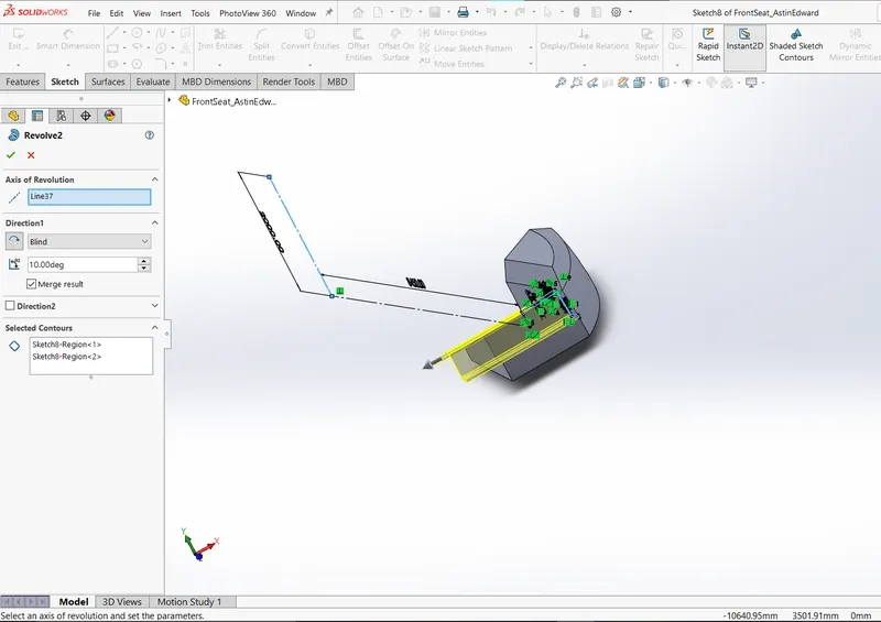
At first glance it looks like a boss extrude but it is in fact revolve extrude feature which utilizes a very lengthy axis to create a desired boss like extrude with a curvature.
6.MIDDLE SEAT
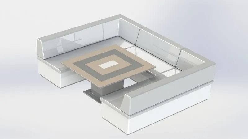
The middle seat designed using solid modelling tools, surface tools are not used while designing this component.
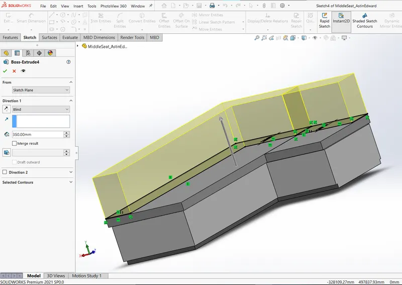
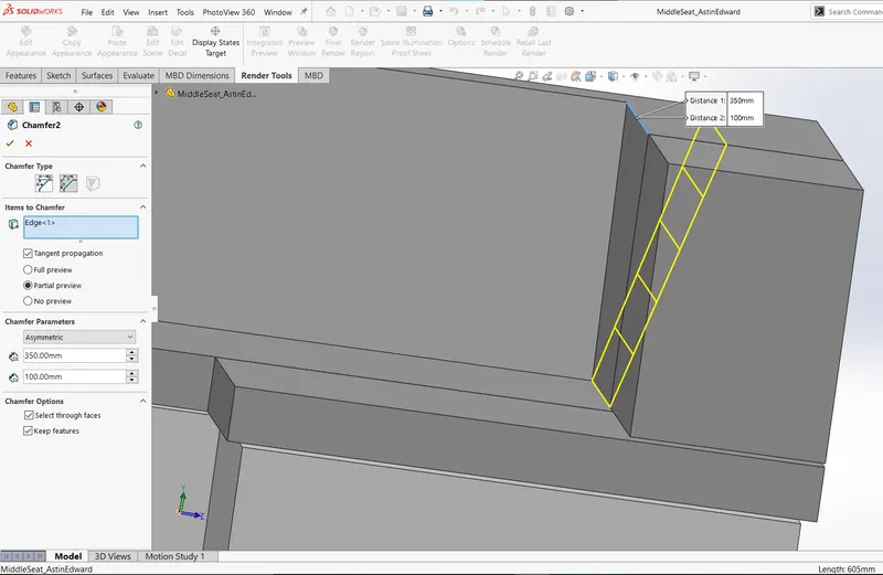
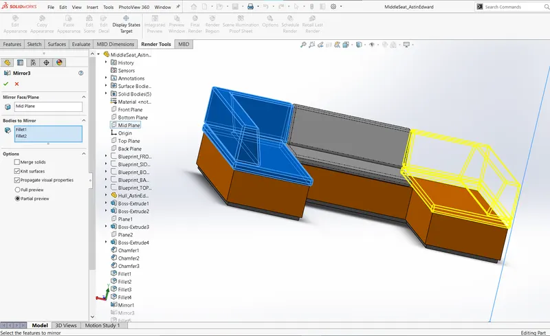
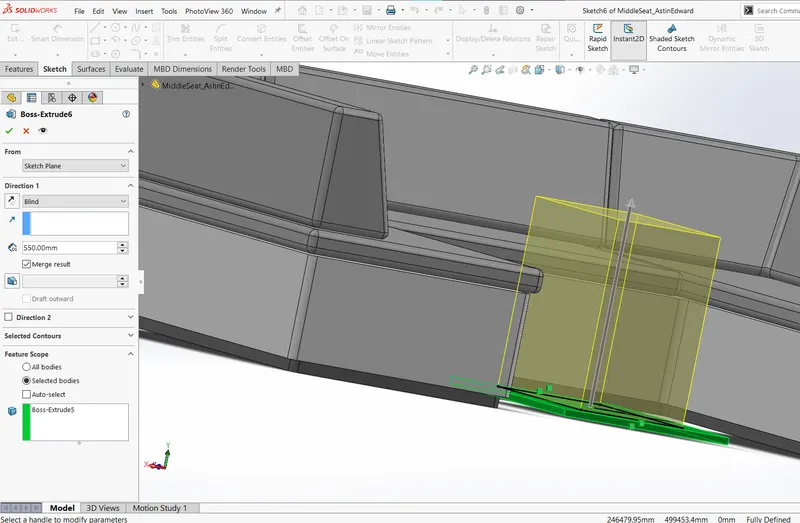
Boss-extrusion, chamfering & filleting and mirror features are used for this part.
7.REAR SEAT
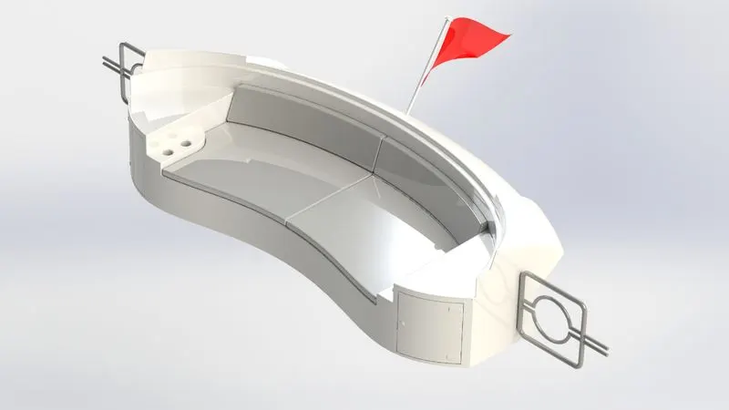
The rear seat is designed using surface techniques like lofting, swept, filling, extension, trimming etc.
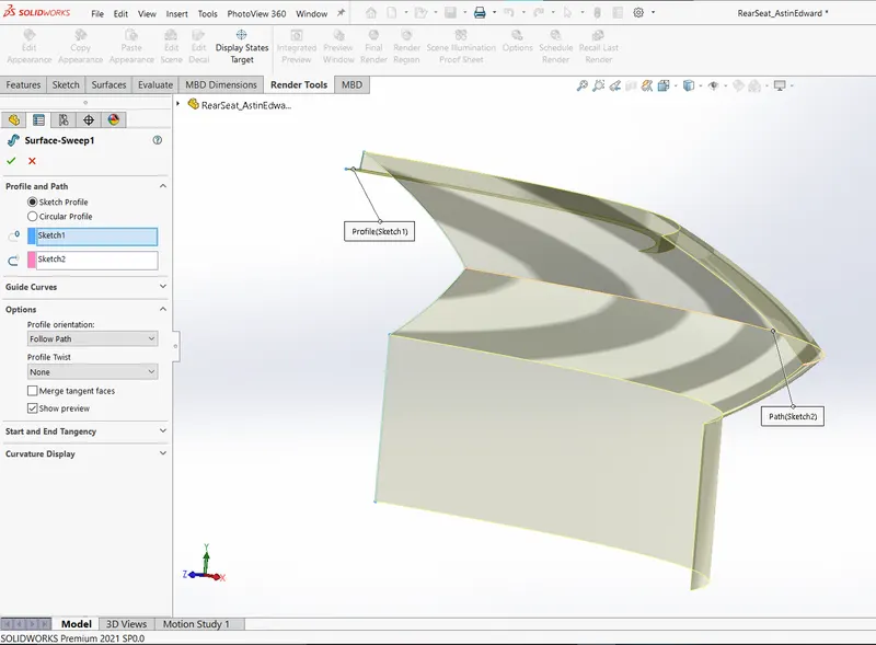
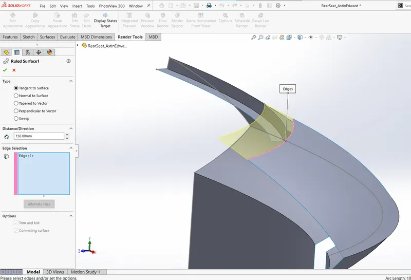
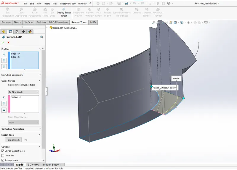
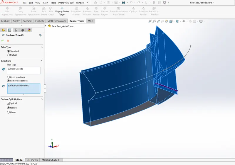
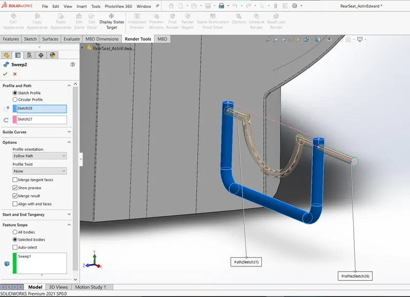
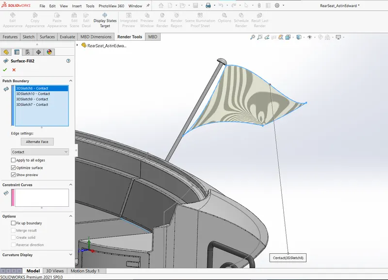
Flag is created from surface filling 3D sketches at the end.
8.SUPERSTRUCTURE
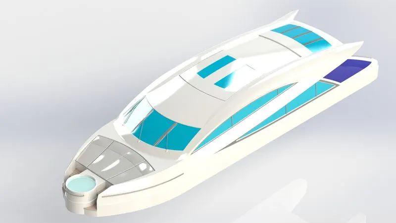
The superstructure is the most comprehensive component to design in the yacht model. It covers almost every surface tools and features.
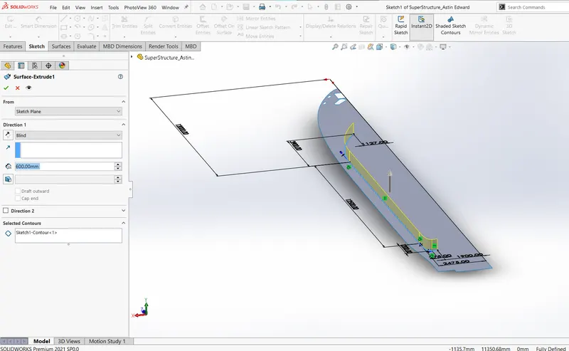
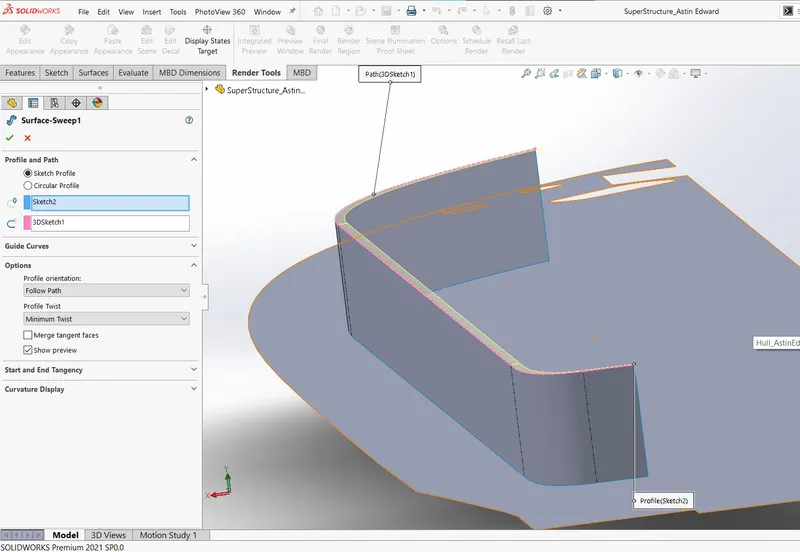
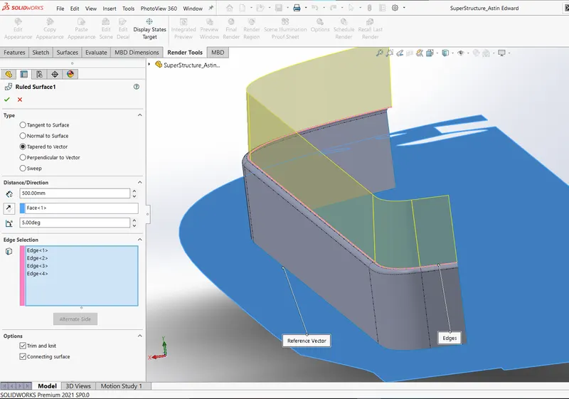
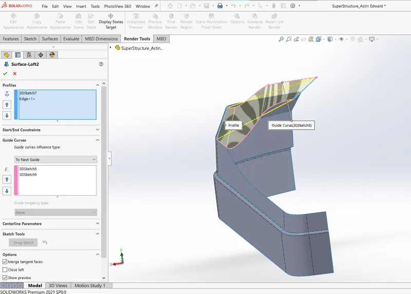
Starting of with surface creation using extrusion, sweeping, lofting and ruled surface.
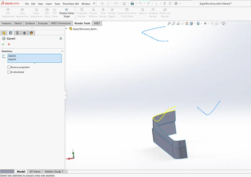
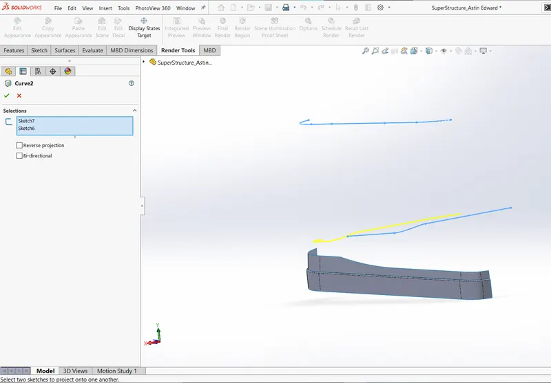
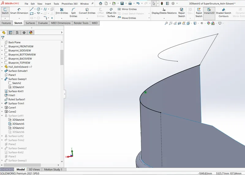
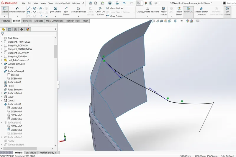
The profiles and guides for the surface tools are created extensively using 3D sketches along with projected curves.
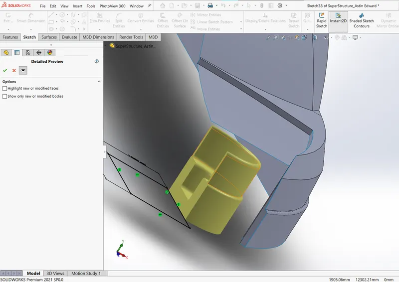
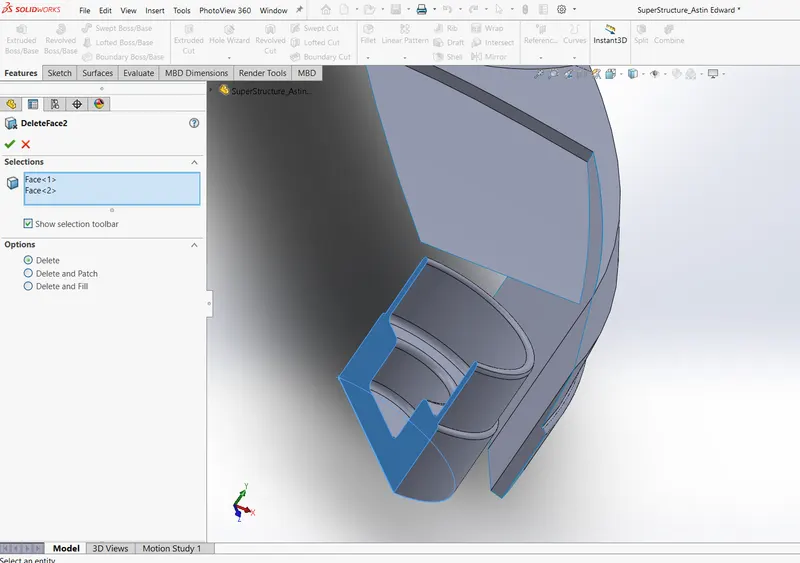
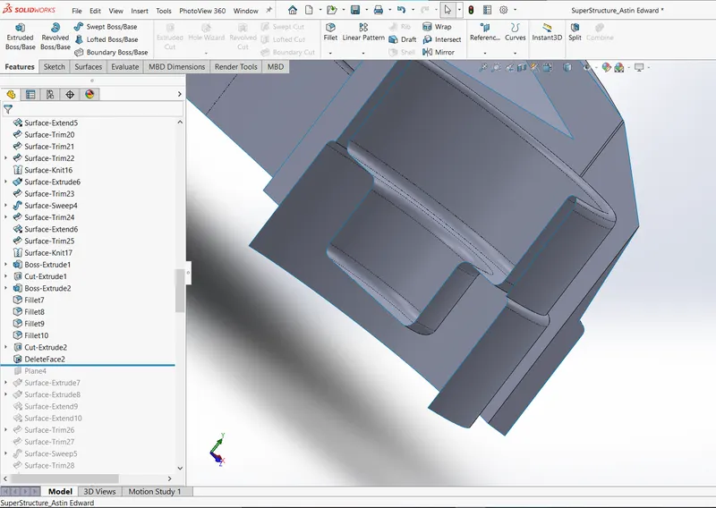
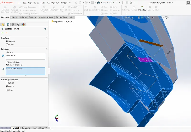
While most of the components are created using surfacing and generally one tend to make solids out of closed surfaces, in case of designing the Jacuzzi, the boss extruded solid body is converted into a surface body using the delete face option. And blends in with other surfaces to create extended surface.
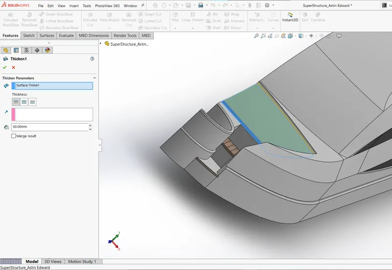
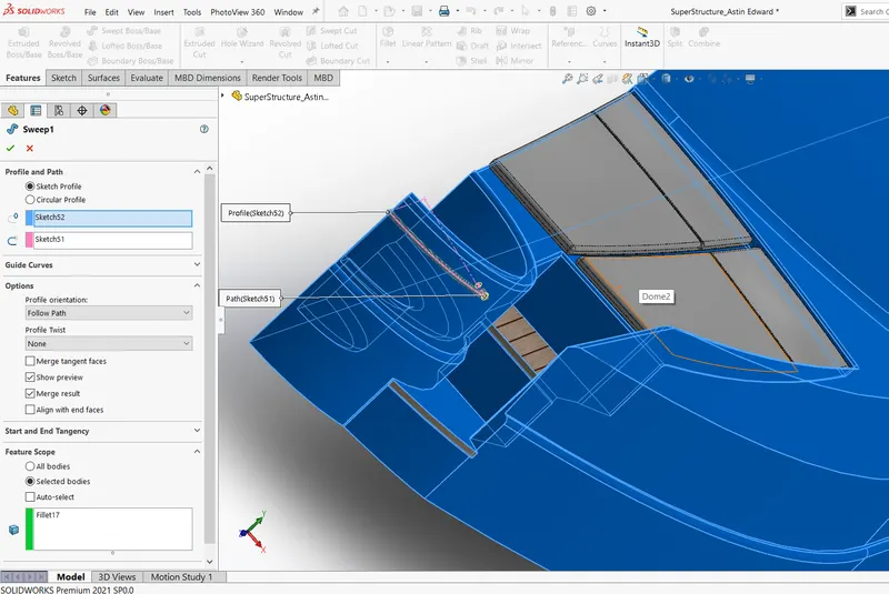
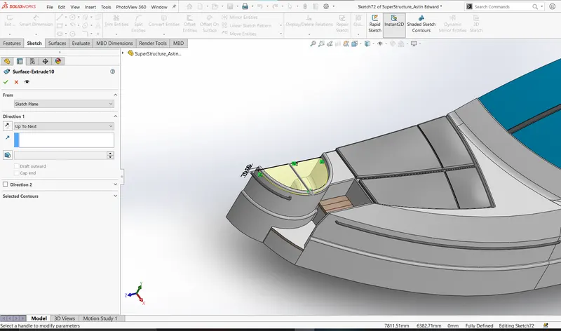
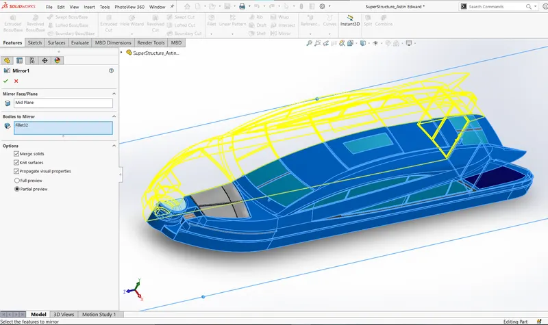
Superstructure is further designed using mentioned surface tools and mirrored to create a solid body.
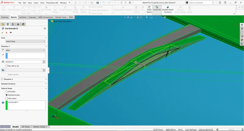
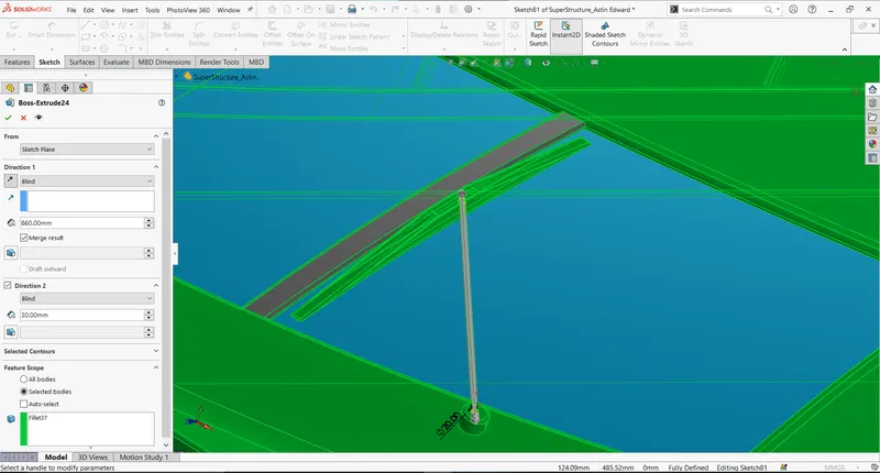
The superstructure is made finally by creating the wipers in the windscreen.
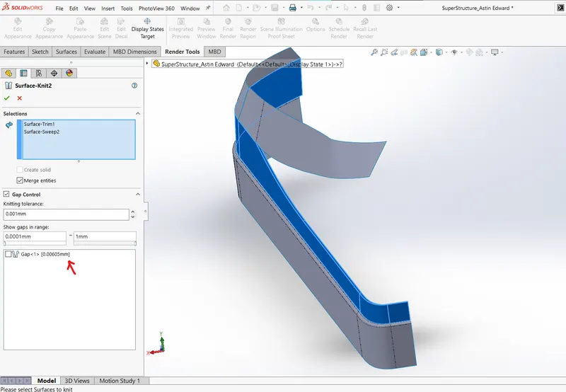
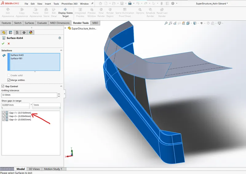
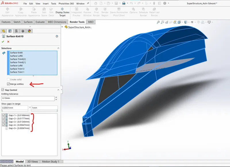
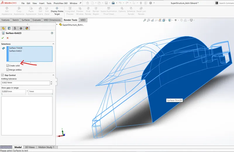
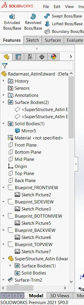
The end aim while surface modelling is to have a closed surface to create a solid body. Often times while surface modelling it is possible that gaps are forming and one must keep a keen eye on the gap values while knitting and merging. The higher the numerical values of gaps the higher the chance that the next surface is going cross the tolerance limit. Sometimes, the guide curves or profiles does not align with the immediate surface. In such a case, once should rollback in the feature tree and modify the sketches accordingly.
- Repair Sketch
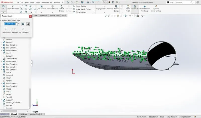
Repair sketch feature can be used to locate the gaps on the sketch.
- Gaps in Range
While using knitting feature under the gaps section one can locate the gaps on the surfaces which needs attention.
- Combine Problem
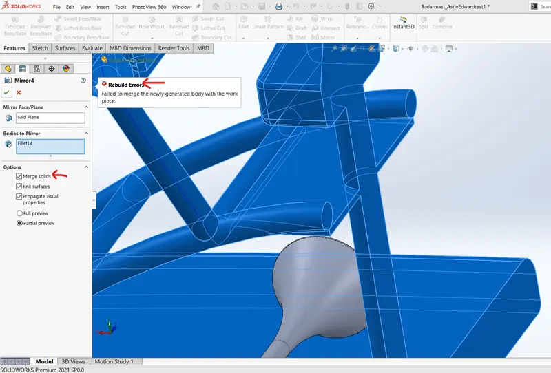
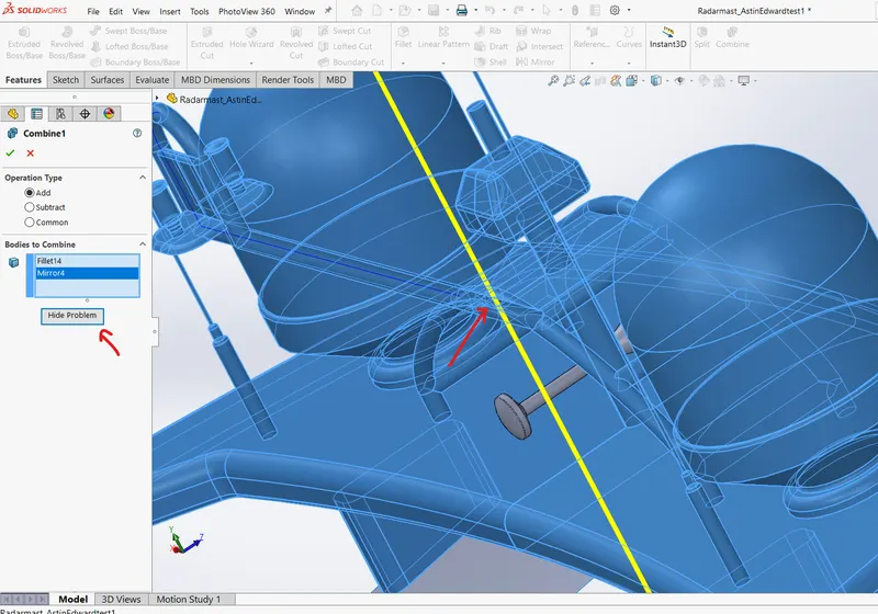
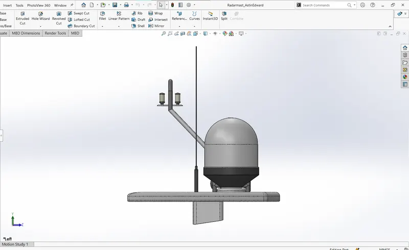
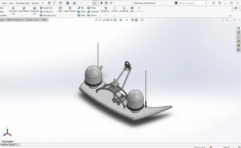
Sometimes it becomes unclear to why some bodies do not merge since so many geometries are intersecting. Proceed mirror by deselecting merge solids and using the combine feature, add the bodies to show preview and most of the times it will show where the problem lies.
9.RADAR MAST
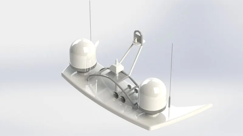
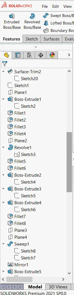
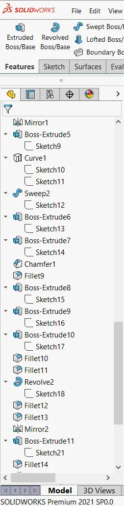
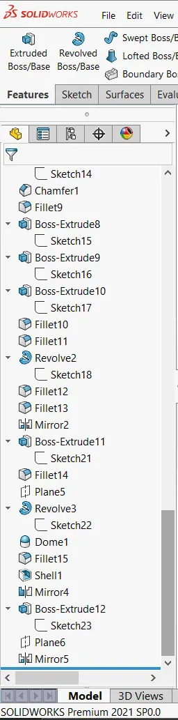
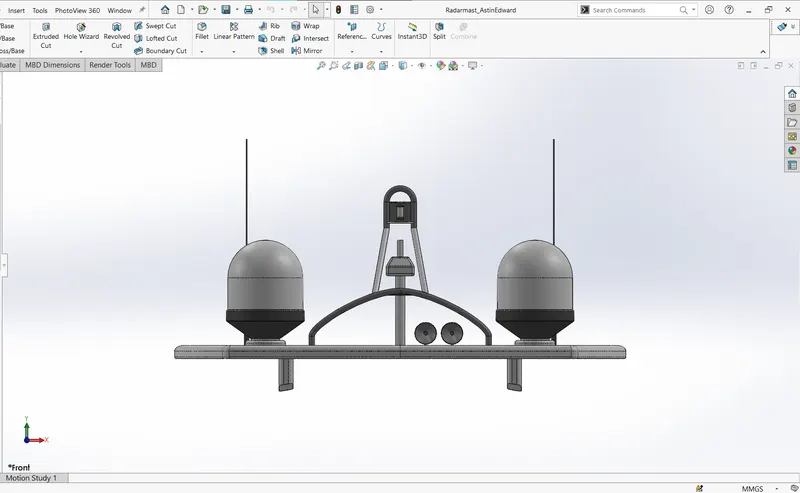
The picture used to sort out the merge solids problem is taken from radar mast part modelling. It is also modelled using the surface tools mentioned for other parts.
YACHT ASSEMBLY:
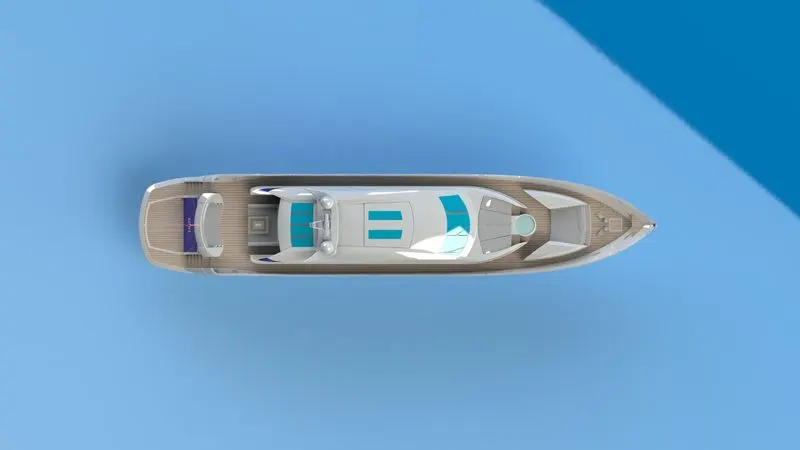
TOP VIEW
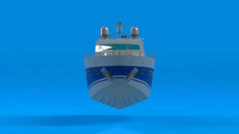
FRONT VIEW
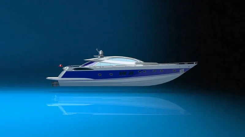
SIDE VIEW
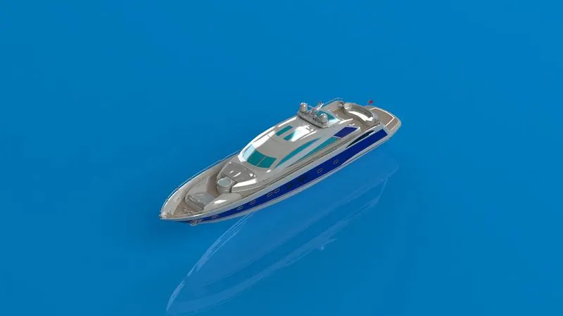
ISOMETRIC VIEW
CAMERA VIEW
BACK VIEW
ALTERNATE VIEW (A)
ALTERNATE VIEW (B)
CONCLUSION
In computer-aided designing, a 3D digital representation of the product is created using various tools but generally a mathematical model needs a parametric design. It is very essential to understand the design parameters of the product to sucessfully create a 3D model and further analysis.
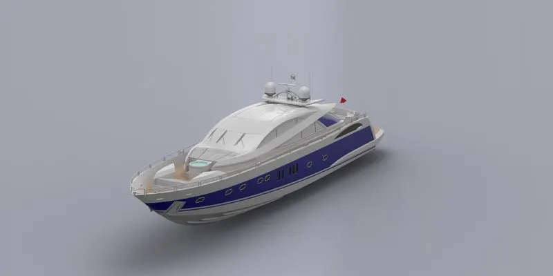
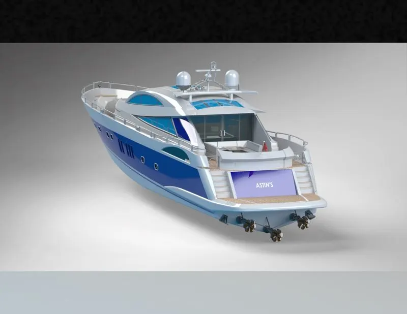
In the previous project solid modelling tools were focused on and in the current project surface modelling tools were focused. The concept is to create a closed surface for creating a solid body while have better options in controlling curvature of our product. But in the end it is the culmination of tools and techniques that make the product more flexible to create and improve design constraints.