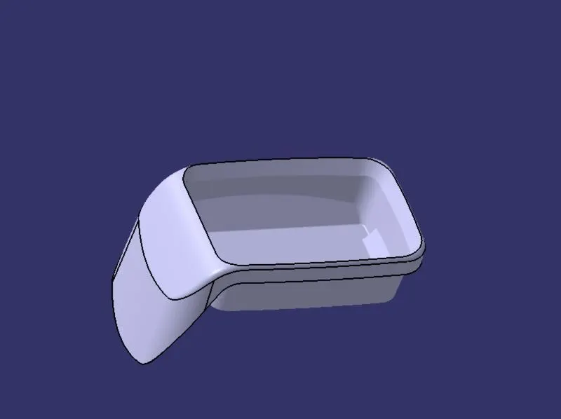
Class B Surface - Coin Holder Design
DRAFT ANALYSIS OF COIN HOLDER
From the given Class A surface we have to make the solid component of 2.5 mm thickness with appropriate draft for manufacturing.
CLASS A SURFACE:
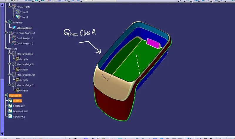
At first the given Class A Surface is evaluated for connectivity and draft analysis.
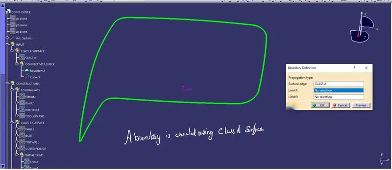
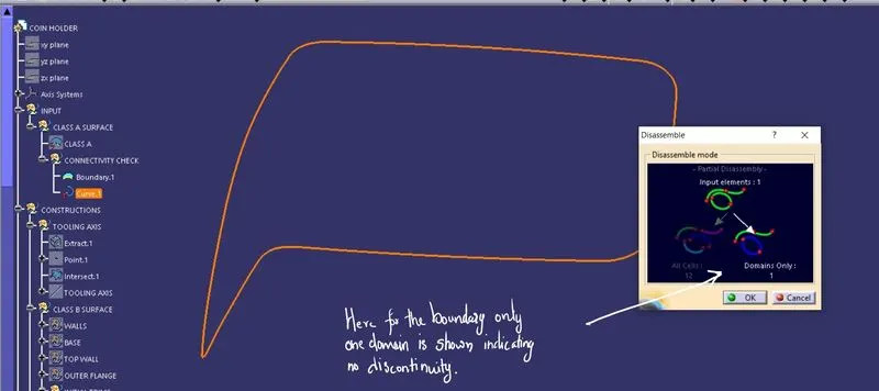
A boundary is created from Class A surface and dissasembled too check its sub cells and domain.
Next step is to create a tooling axis for draft analysis. For this purpose, a geometrical set is created for tooling axis reference construction.
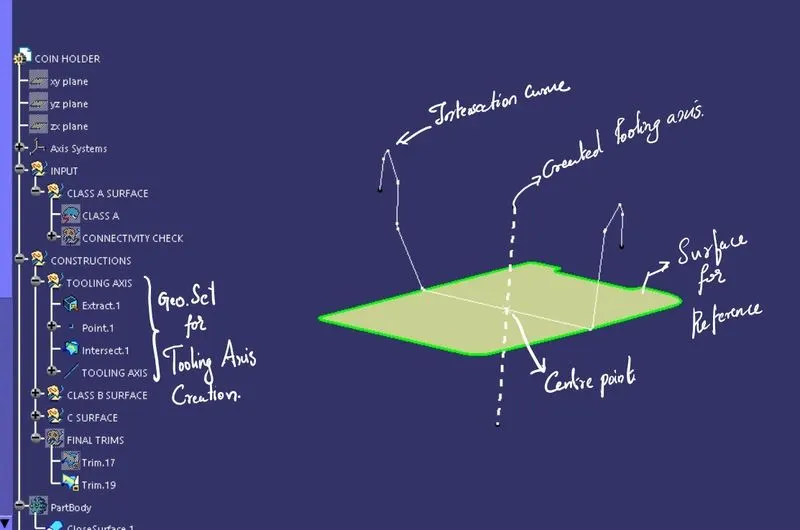
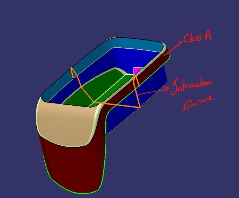
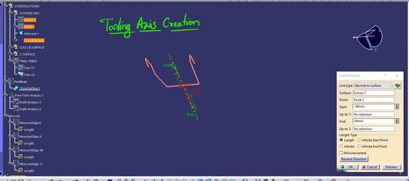
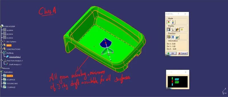
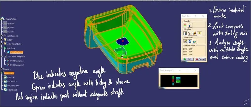
Generally, tooling axis is created using bisecting tool taking both extremes of sloping line along the taken reference direction say, z axis of the system. Tooling axis should be oriented in such a way that it offers minimum side core and under cut action and possible to provide draft to every component. Drafting of the component is necessary for proper ejection of molded componets and for ease of manufacturing. A minimun of 3 degree draft is required and while designing the components a maximum of 0.003mm limt is said to have for close tolerances like merging surfaces.
Draft analysis of Class A surface:
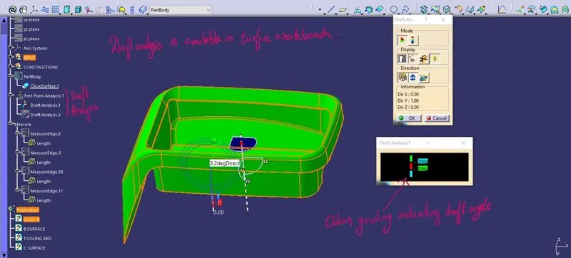
Draft analysis of part body:
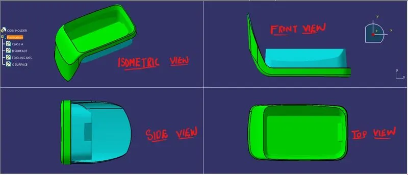
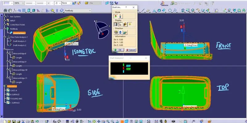
Different views of part with draft colour grading:
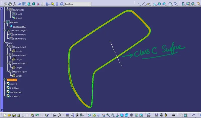
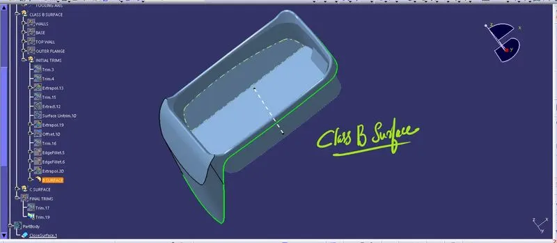
Created Class B and Class C:
Class C:
Class B:
Modeled Component using closed surface tool: