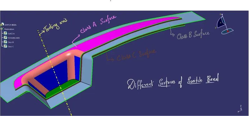
Switch Bezel Design
DESIGN OF SWITCH BEZEL AND DRAFT ANALYSIS
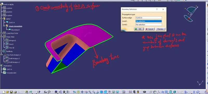
Before anything else, we have to check the connectivity of Class A surface. It can be done using either join tool or disseasmbling elements after boundary tool for proper analysis. After checking for connective surfaces, we need to analyse the component on differet planes to identify the tooling axis. Tooling axis should be oriented in such a way that it offers minimum side core and under cut action and possible to provide draft to every component. Drafting of the component is necessary for proper ejection of molded componets and for ease of manufacturing. A minimun of 3 degree draft is required and while designing the components a maximum of 0.003mm limt is said to have for close tolerances like merging surfaces.
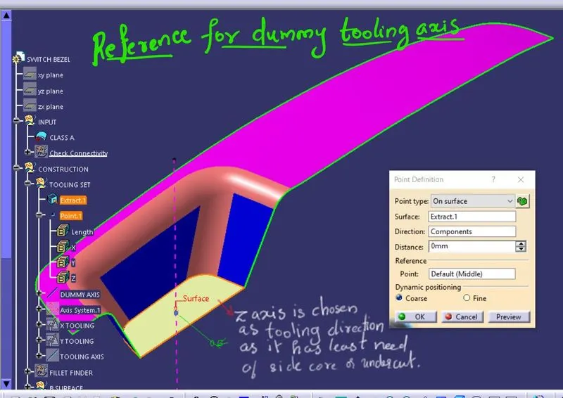
The reference of tooling axis after visually analysing is taken as z-direction. Next step, a surface is selected to create base reference point (if holes were present, one of their centre point would have taken).

Next step is to create axis system (or reference planes) for making intersection curves with X-plane and Y-plane.
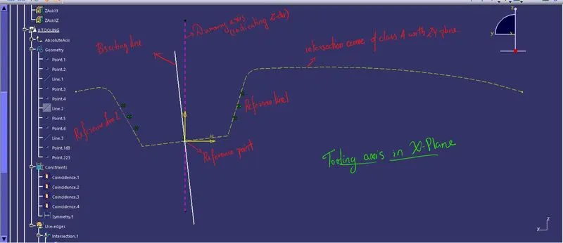

These curves helps us in making our tooling axis properly oriented to provide draft to whole component.
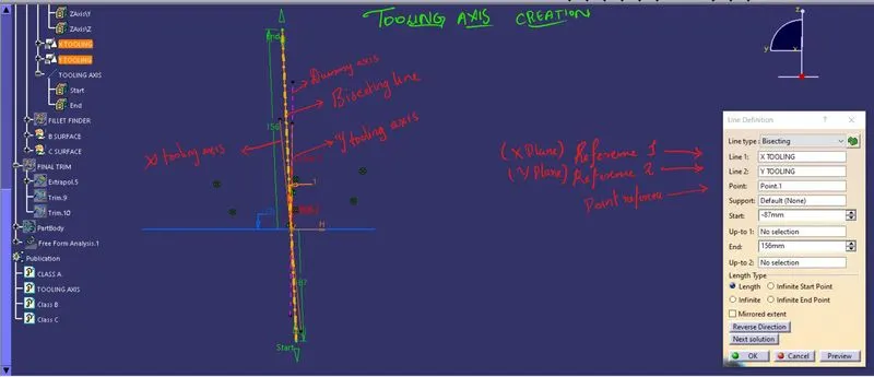
Taking the reference of the two tooling axis in x and y plane, tooling axis for the component is created bisecting both. Daft analysis can be once done after creating the tooling axis. A first analysis is done on Class A surface for better understanding of slopes and geometry and to check whether its manufacturable.
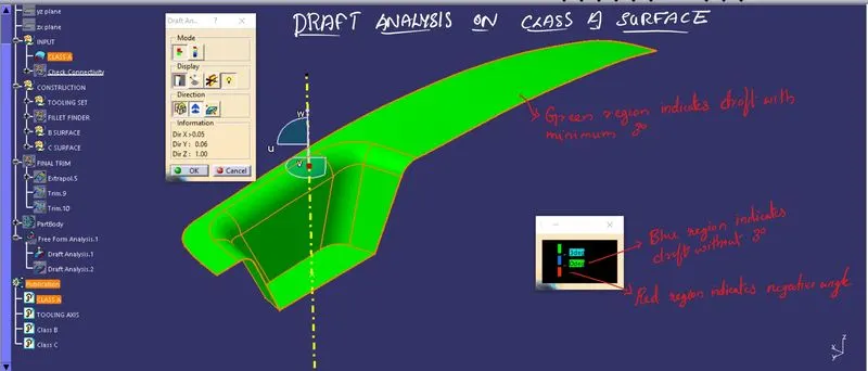
Draft analysis is done on the body finally after creating Class B and C surfaces.
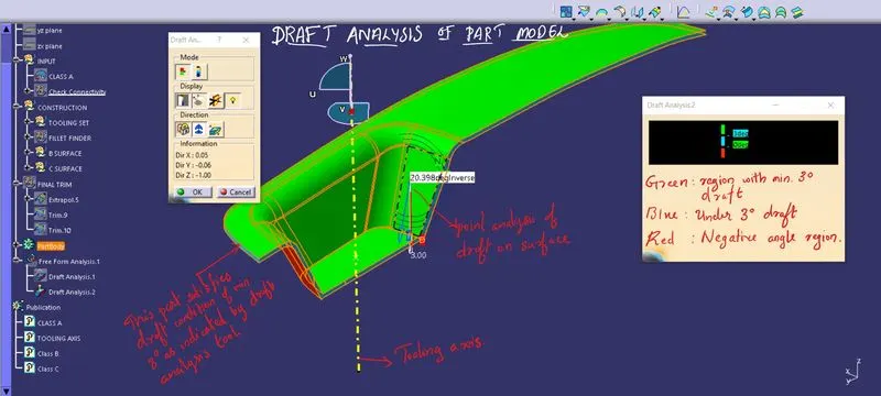
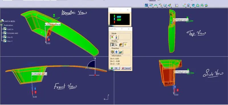
Creating a closed contour from thoses surfaces, using close body tool one can form solid component from theses sketches. Below images are screenshots of the solid model with the proper color code of the draft angle in various orientations (Isometric, Front, Side, and Top View).
CLASS A, CLASS B, CLASS C Surfaces: