Wiring harness design in CATIA V5 - 3D modeling Week 7 Challenge
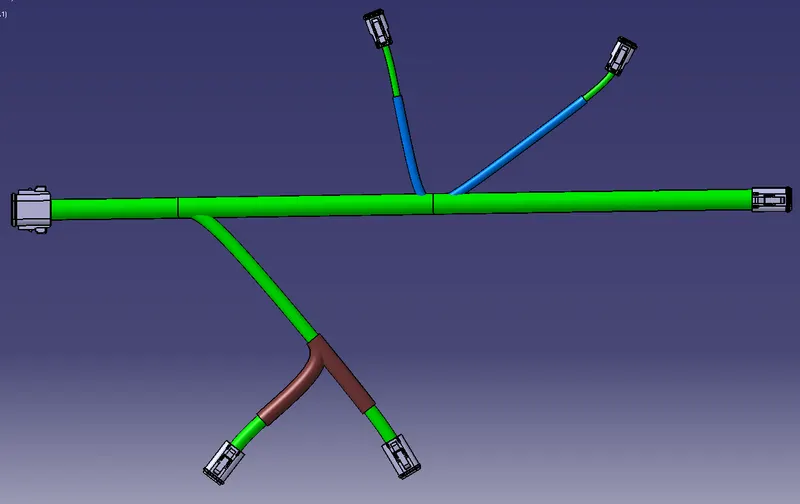
The above image shows the harness from week 4 challenge. To create the flattened view and the harness drawing following steps have been carried out.
Create a new product file and open electrical harness flattening workbench.
Choose Harness Flattening Parameters and under general tab check for Algorithm mode, angle mode and minimum angle between two branches set to 20deg and activate the keep existing tangency and choose radius of the bundle segment.
In drawing tab > let it be default. Rename and save the drawing in the same location where the main file has been saved.
Open both harness assembly and Harness Flattening Parameters tab and tile vertically.
Keeping Electrical harness flattening workbench active select the extract icon and choose the harness assembly geometrical bundle.
The harness assembly will be extracted with the _Ehf extension file name into the Electrical harness flattening workbench.
Now select flattening and choose the flattening plane and select any branch and choose the select all branches tab from the pop-up.
Arrange the branches accordingly using the manipulation tools like rotate, roll etc.
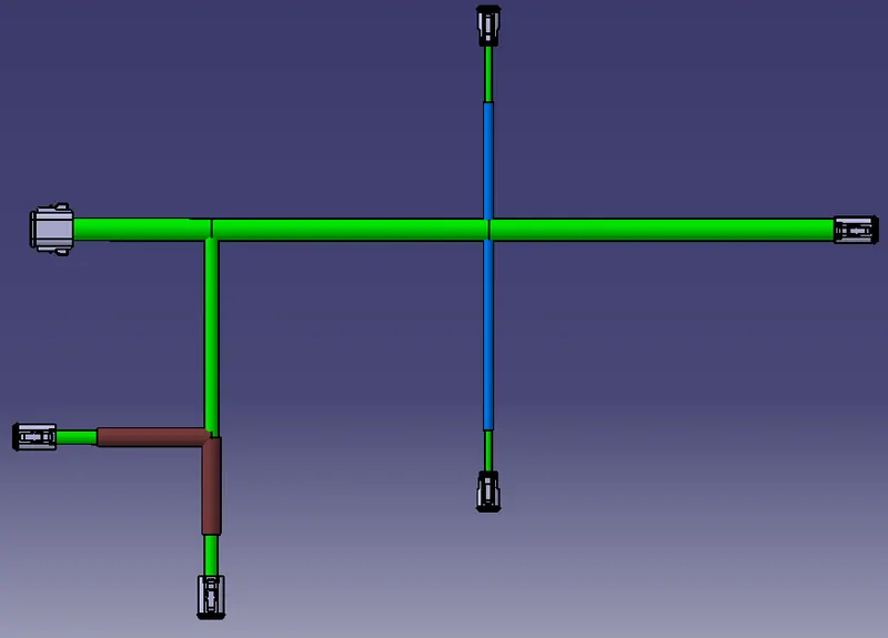
Once the flattening is done the harness assembly looks as show in the above image.
To create the drawing file New > Drawing > ok
Select the standard sheet type, size, layout etc. Rename and save the drawing.
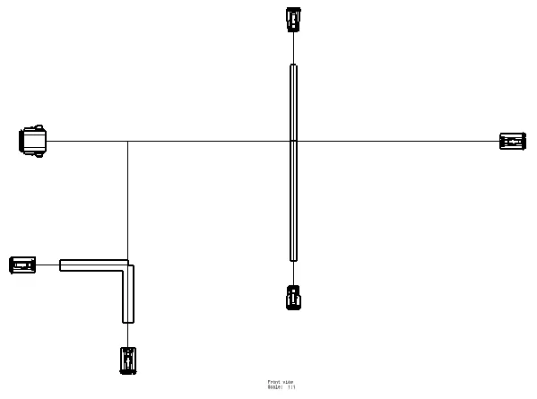
From drawing workbench, click on add front view and tile vertical to select the surface or plane selected during flattening process.
Drawing will be in floating condtion, orient and allign the drawing accordingly and click on the empty space to drop the drawing in the sheet.
If any lines are missing data, right click the selected drawing and choose properties and in view tab under dress up choose for 3D wireframe and is always visible option.
In this drawing single and double line is selected for bundle and protective coverings respectively.
The drawing with dimensions is attached.