Project 1
The Engine CAD data is downloaded from the given link.
The CAD model is made as an sub-assembly of Engine Harness Context Assembly.
Another product file added in the main context assembly is Engnie harness geometrical bundle in which all the wiring harness data is available.
L Clamp is added in the main context assembly as it is not the part of wiring harness assembly and it is treated as surrounding data.
All the connectors, P clamps, clips and channel are downloaded from the provided link and are electrically defined in electrical part design workbench.
The positioning of the connectors is carried out in the engine harness geometrical bundle assembly as it is the part of harness assembly and the reference data is from the engine CAD data.
After positioning all the mating connectors in the required positions. The decision of placing the p-clamps or clips as per packaging rules and industry best practices is finalised. the mounting of the clips and clamps is taken care by using the available fastening locations or by suggesting for the tapped holes at the possible locations.
After all the necessary conditions and rules have been applied in the positioning, the later stage is to start with the routing of the bundle considering the entry from one side as the inter-connection point from where the engine wiring harness starts.
Once the routing is started, the minium distance of 50 mm between each branching points is maintained.
Routing in the channel is carried out by providing an external curve option.
The diameter, branch points and slag percentage requirement for the particular wire is mentioned and for each branch the parameters are set.
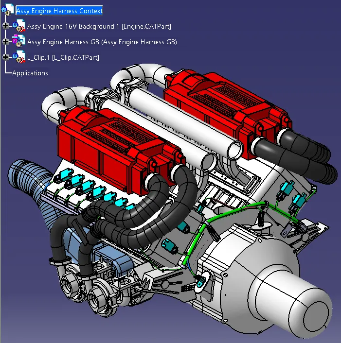
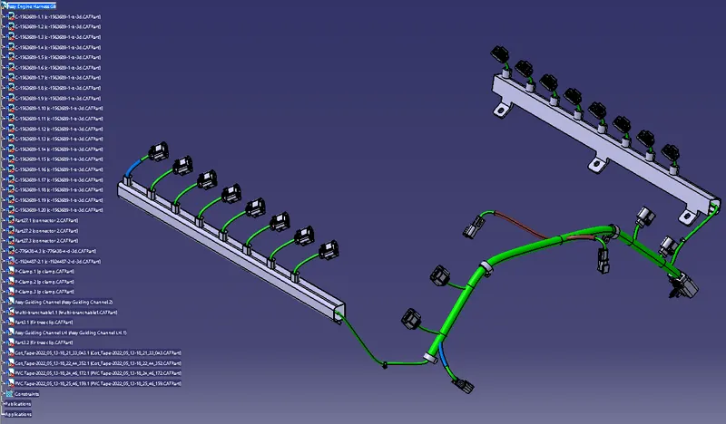
The Wiring harness geometerical bundle assembly is as shown in the below image.
All the visible components and connectors are part of harness assembly and should be available in the harness drawing.
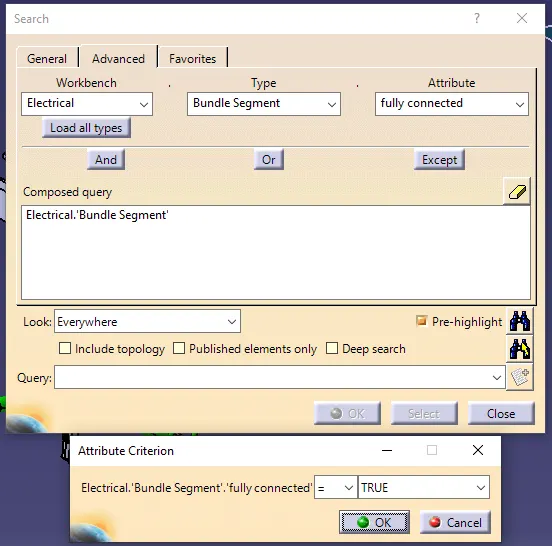
The Bundle continuity check is carried out in-order to confirm the connectivity between all the branches, connectors and main trunk.
By setting all the parameters as shown below, we are able to get all the connected branches.
The bundle continuity report is attached, and the continuity is 100%.
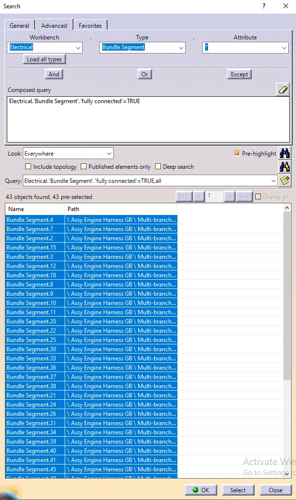
Since there are no errors, we can proceed to flattenig.
Initially the electrical harness flattening parameters are set and the required parameters are selected.
A new drawing file is created and the harness assembly is is extracted from the flattened file.
The drawing is checked for errors. the drawing file is as show in the below image.
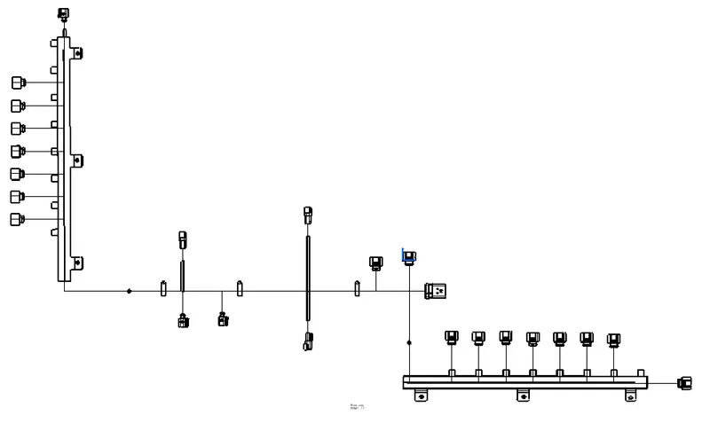
All the files, catalogs, CAD data, assembly files and drawings have been attached.