Wiring harness design in CATIA V5 - 3D modeling Week 7 Challenge
Flattening and Engineering Drawing – Wiring Harness
Wiring harness design in CATIA workbench utilizes 3D workspace and 3D components. In the assembly and manufacturing section it is essential that these data are converted to 2D workspace and necessary information is saved in the process.
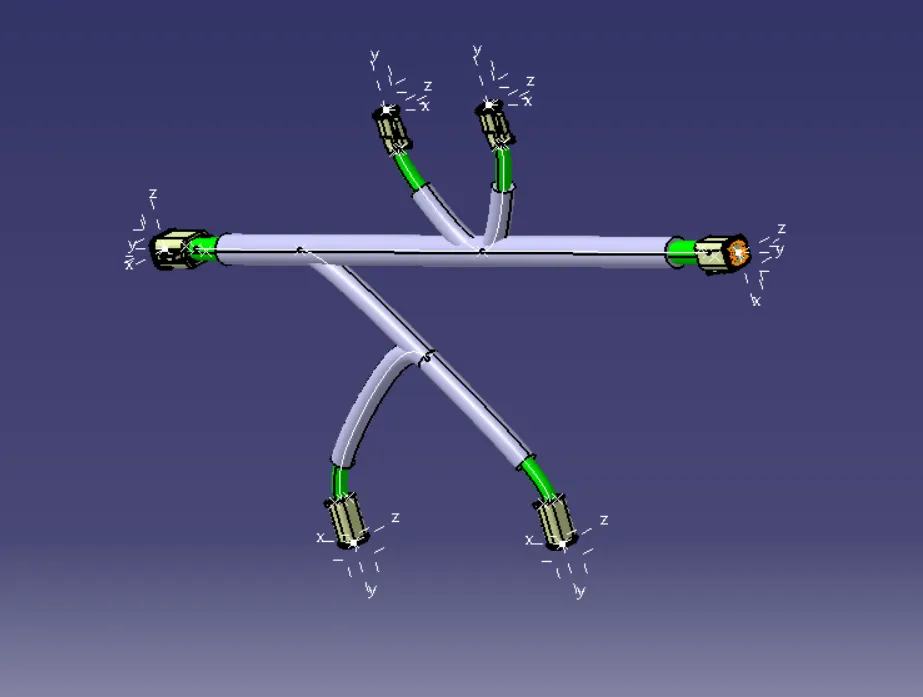
The above picture showcases the 3D product of harness.
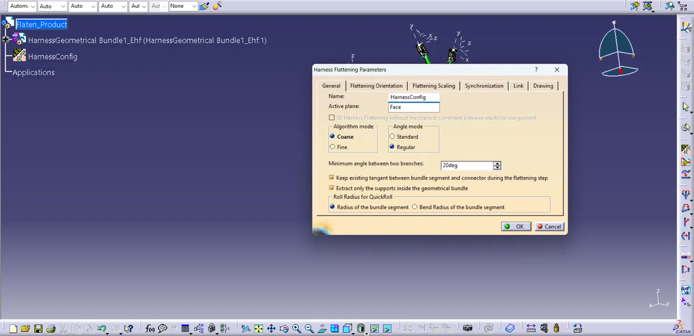
In order to convert the 3D data to 2D counterpart we utilize “Electrical Harness Flattening” workbench. The first step in activating this product workbench is by defining the Harness Flattening Parameters, which include 3D representation lines (double/single), algorithm mode (coarse/fine), orientation (active plane etc.), drawing characteristics etc.
The picture below shows the parameter data of the Harness Flatten, the subsequent snaps show flatten and rotate tool in action for proper arrangement.
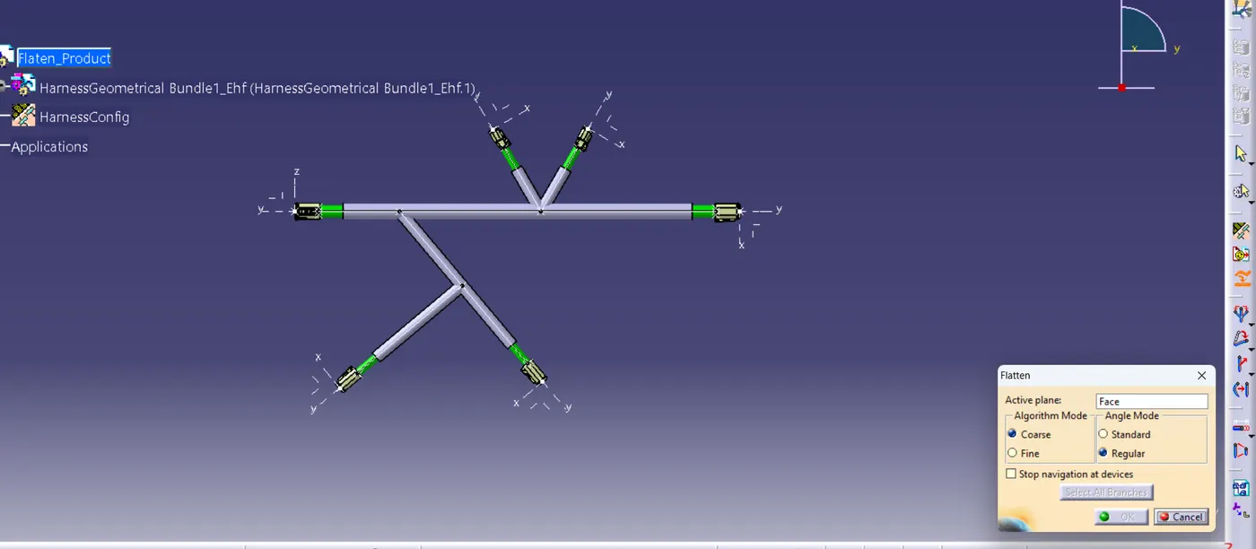
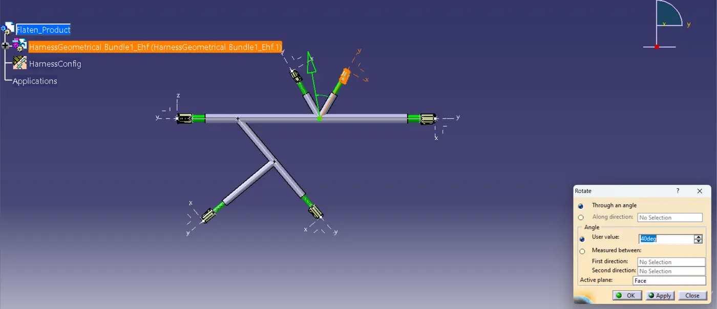
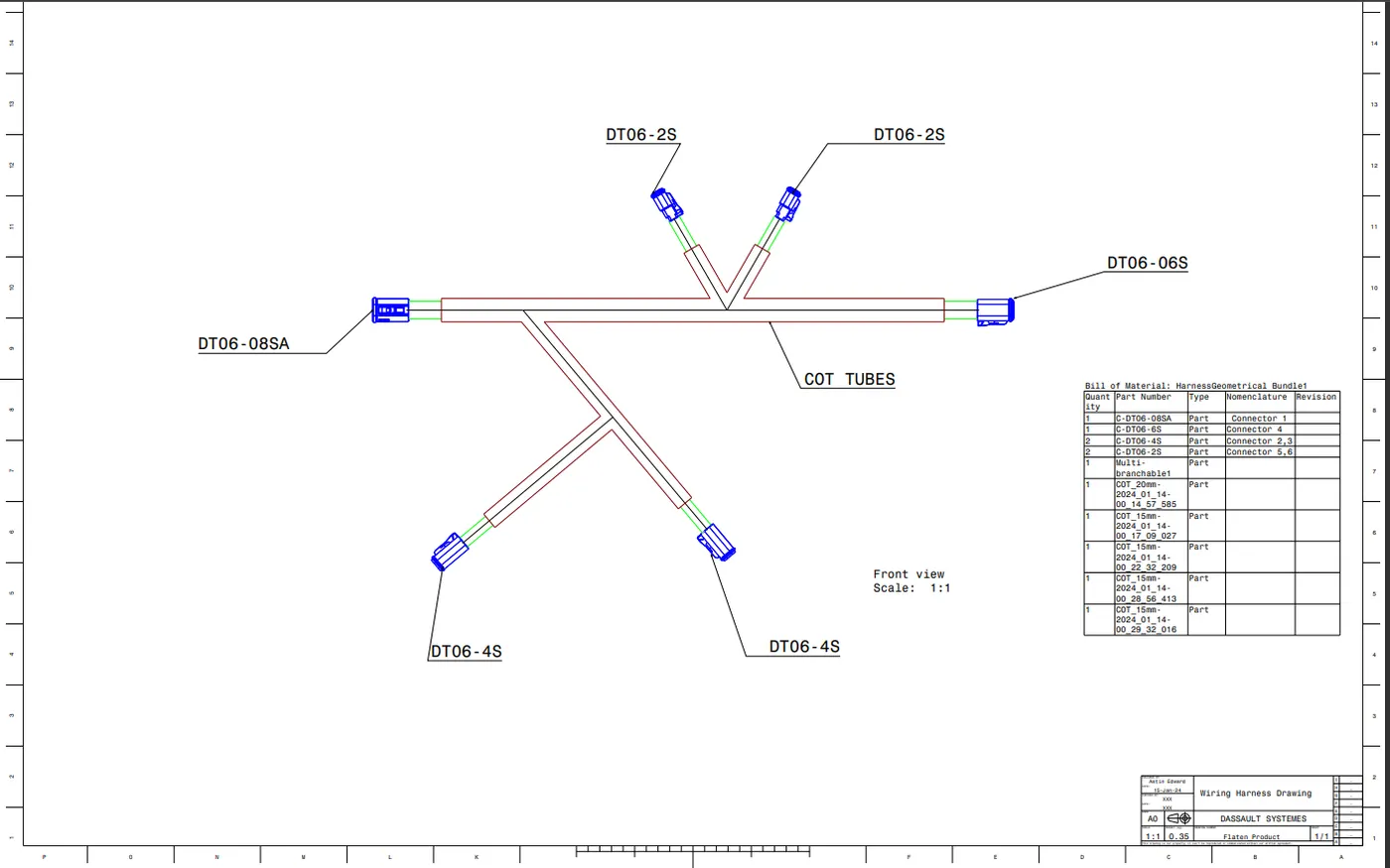
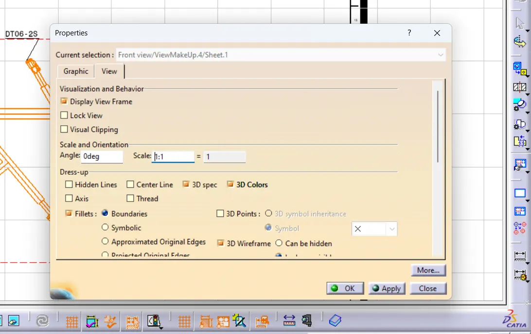
After the necessary flattening operations, a new file for drawing is created. “Front view” tool is used to import geometry form Flatten product. Subsequent properties are changed to get the user desired output. Annotations and colors are added to the drawing for better understanding of the drawing.
Bill of materials and Title Block are added under “Sheet Background” workspace conveying necessary details of the wiring harness.
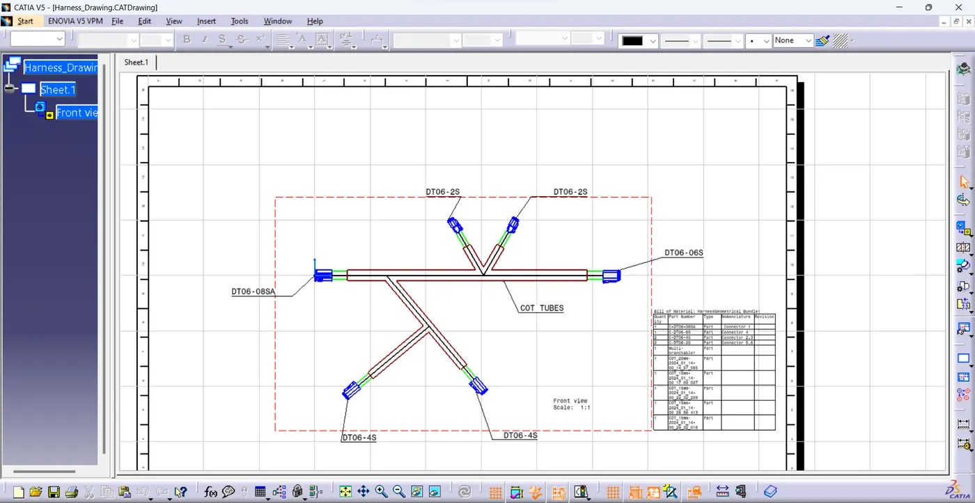
The final output of drawing in pdf format is shown below;