Wiring harness design in CATIA V5 - 3D modeling Week 7 Challenge
Wiring harness design in CATIA V5 - 3D modeling Week 7 Challenge
AIM :
To prepare the flattened view of wiring harness assembly using the Electrical harness Flattening workbench and place it on the drawing sheet.
INTRODUCTION :
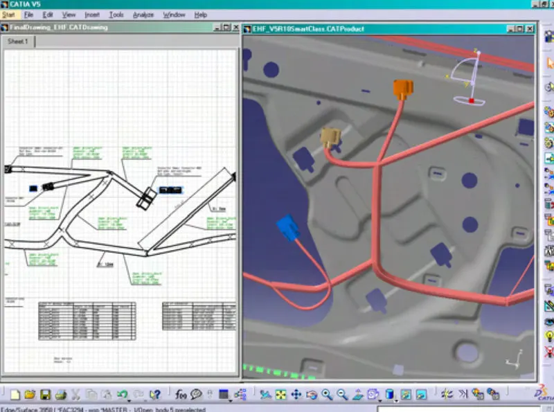
Once a product is ready to manufacture, its design must be precise or it risks costly errors and delays. Collaboration is the essential key to successful documentation and design between harness designers and manufacturing.
CATIA – Electrical Wire Harness Flattening provides automatic and complete flattening of 3D Electrical Harnesses for manufacturing documentation in a concurrent engineering environment.
Customer Benefits
- Seamless collaboration between harness designers and manufacturing to ensure accuracy of 3D information transferred to manufacturing
- Best environment for harness detailed manufacturing documentation and form-board design
- Reduce effort for generation & maintenance of 2D harness drawings
- Integrated design to manufacturing process with the support of design changes
- Reduce cycle time with the ability to reuse existing documentation
OBJECTIVE :
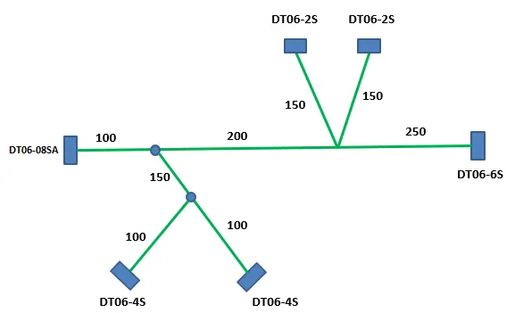
- Define the mechanical parts electrically and prepare create a harness assembly with reference image.
- The harness assembly has to flattened in the CATIA flattening workbench.
- Create 2D drawing of the bundle with connector representation and different colour coding for bundle with protective covering.
DESIGN METHODOLOGY
STEP-1
Procedure of the connector for defining it electrically.
Download the required Connectors from the source and convert the mechanical connectors electrically by using the electrical part design work bench by following below steps.
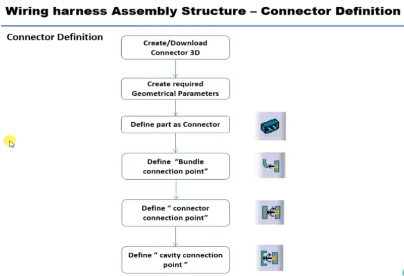
- First download the connectors and mounting clip from the given link source.
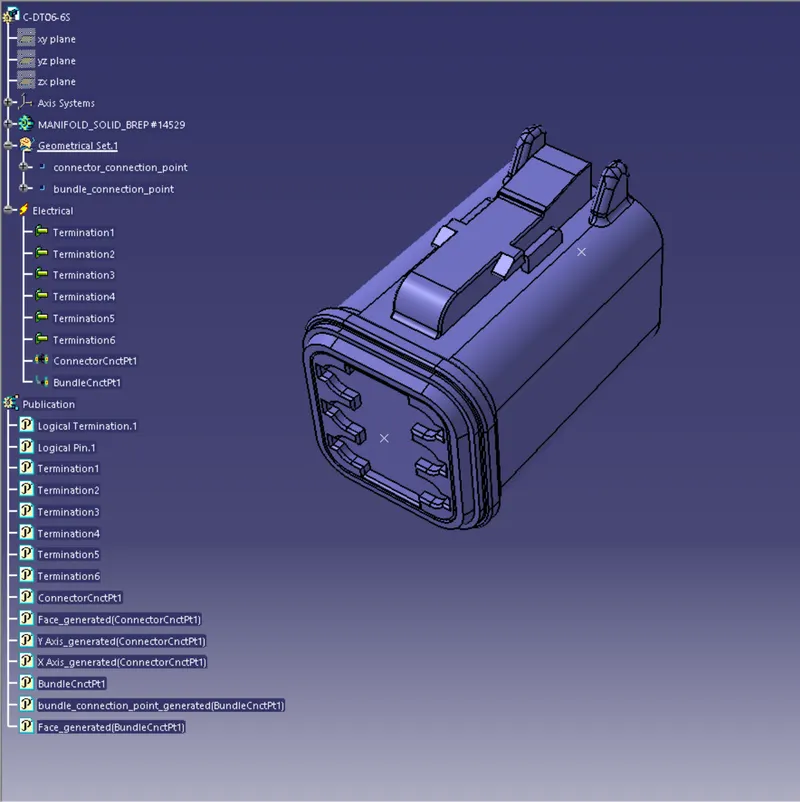
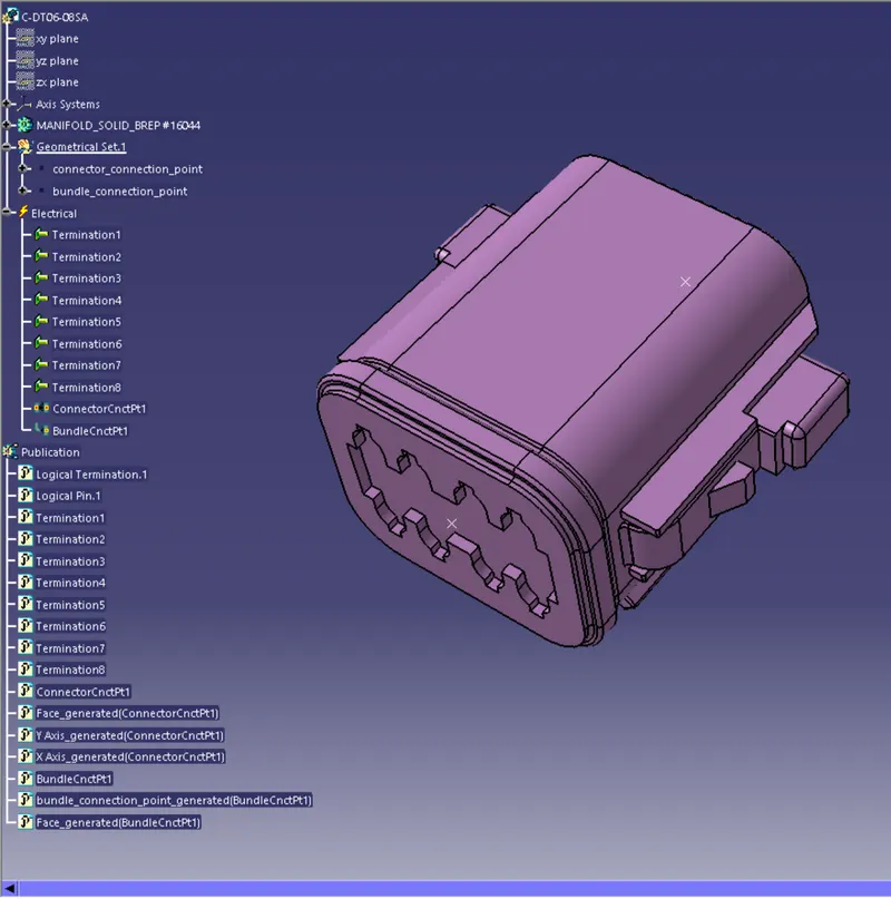
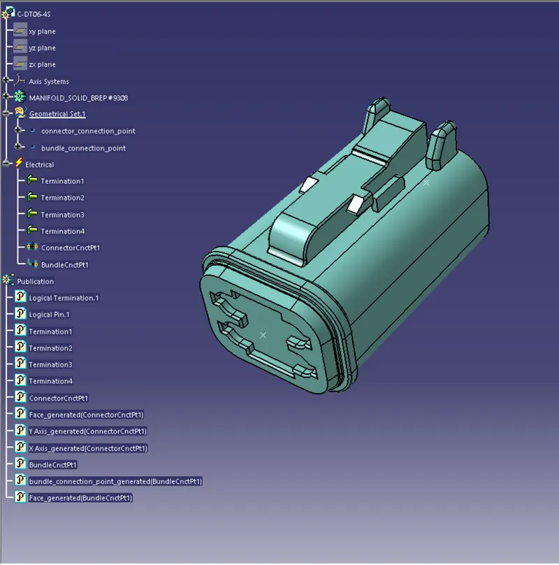
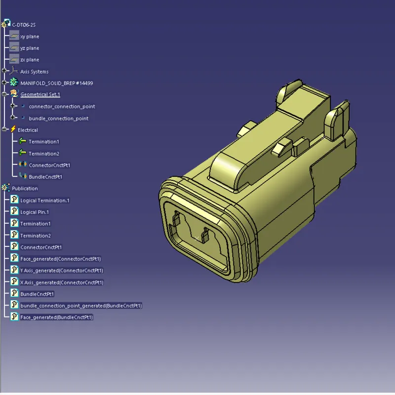
- Get into the mechanical part workbench to create required geometrical parameters. Create connector connection point and bundle connection point on the required sides of the CAD part.
- Create axis system on the connector connection point such a way that the Y coordinate facing normal to the connector face, X coordinate facing towards the locking mechanism and Z coordinate facing to the top.
- Create cavity connection point for connectors having the cavity for mounting clips
Using the geometrical parameters created,
- Define part as electrical connector.
- Define bundle connection point.
- Define connector connection point.
- Define cavity connection point.
STEP-2
Procedure for creating the harness
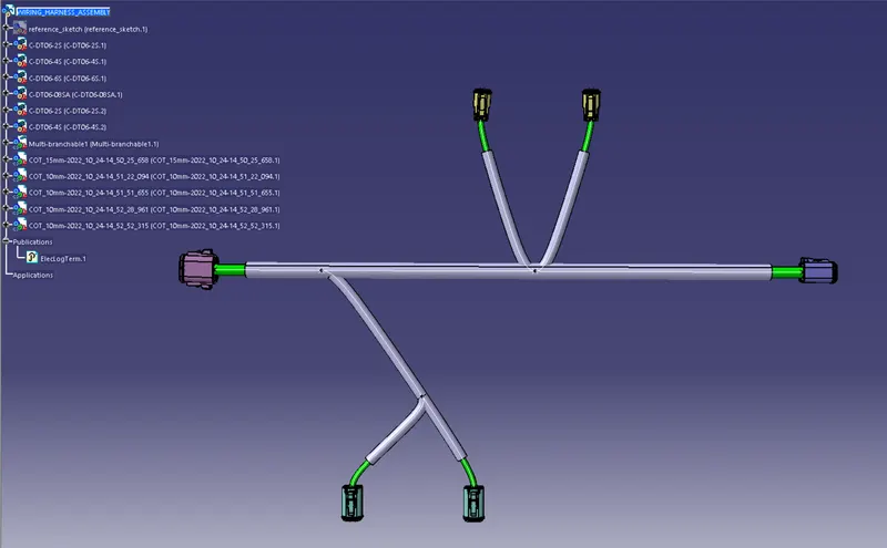
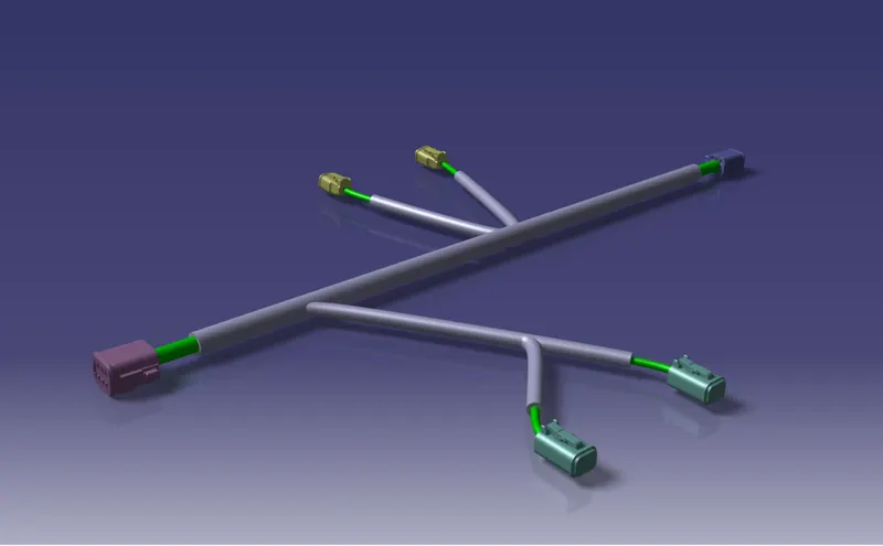
- Create a product fine and define it electrically using Geometrical Bundle option
- Create a reference drawing part for proper alignment of connectors.
- Using Snap, move and compass place the connectors at desired locations
- Bundle segments are created with connectors bundle connection points. (Bundle diameters are assumed as 10mm and 5mm)
- Create branch point on the main multi branchable bundle.
- Create sub multi branchable segments.
STEP-3
Harness Flattening Procedure
- Harness flattening can be created from the Electrical Harness Flattening Workbench in CATIA V5.
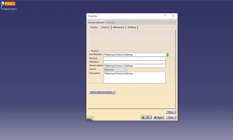
- Create a new product file in the Electrical Harness Flattening workbench and rename it as of our requirement.
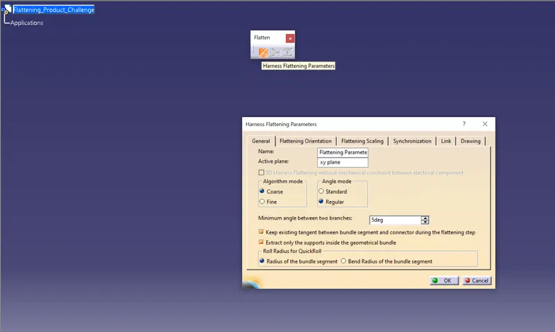
- Select the product file and define Flattening parameters to it. And we can rename it as of our requirement.
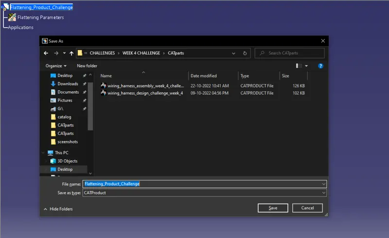
- Save the flattening product file in the save folder which is having all the other required documents.
- Create vertical windows with Harness assembly product and flattening product files.
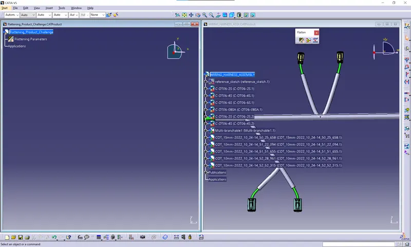
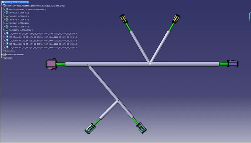
- Using the Extract option, extract the harness assembly into the flattening product.
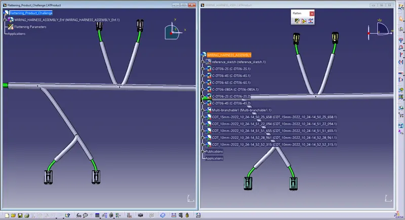
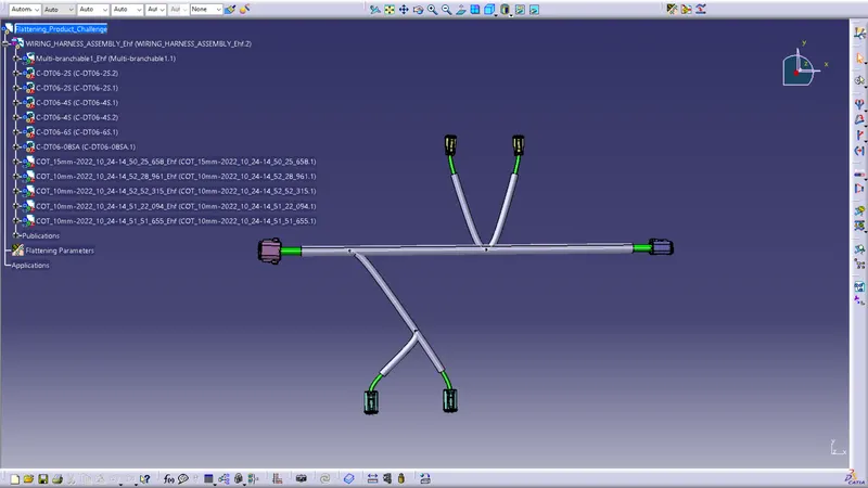
- Convert the extracted harness assembly into the flattened harness assembly by using the Flatten commend.
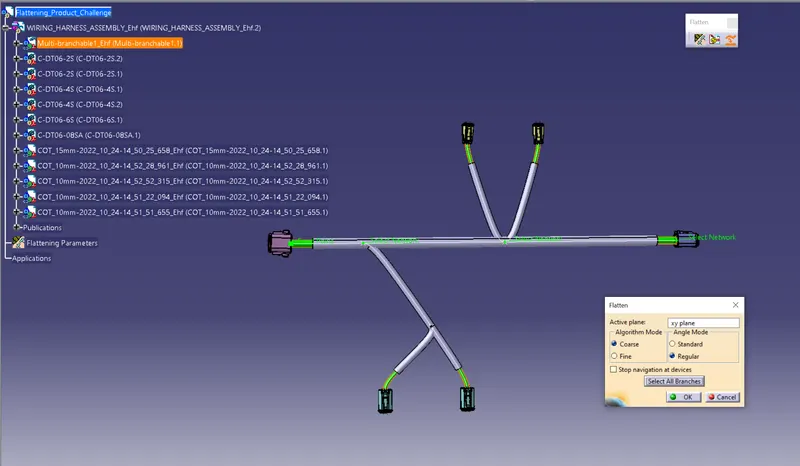
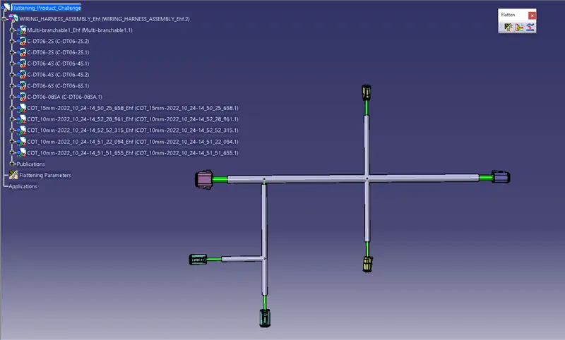
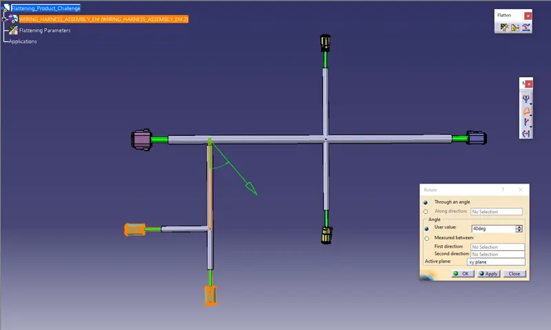
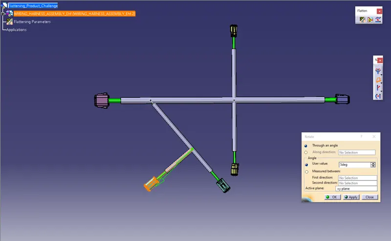
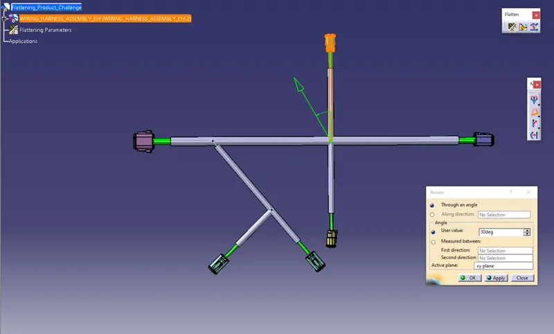
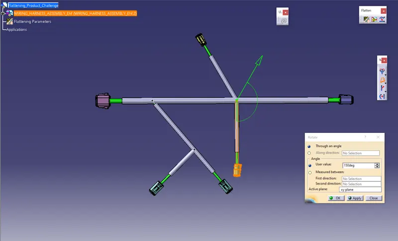
- Rotate the flattened bundle segments to the desired directions using the Rotate command and manually update the product to update the changes occurred during the rotate command.
STEP-4
Create a Drawing File for the flattened harness product.
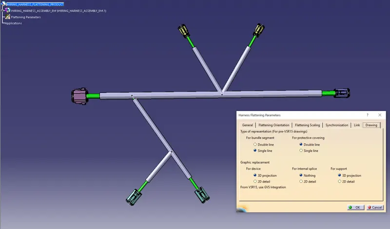
- First, we need to make sure that in the flatten parameter settings bundles and protective coverings have different graphical representation which are,
Bundle Segments – Single line representation
Protective coverings – Double line representation.
- Create a new drawing file in the drafting workbench
- Modify the drawing sheet with required parameters.
- Insert the flattened harness product into the drawing sheet using view option and selecting the front view command.
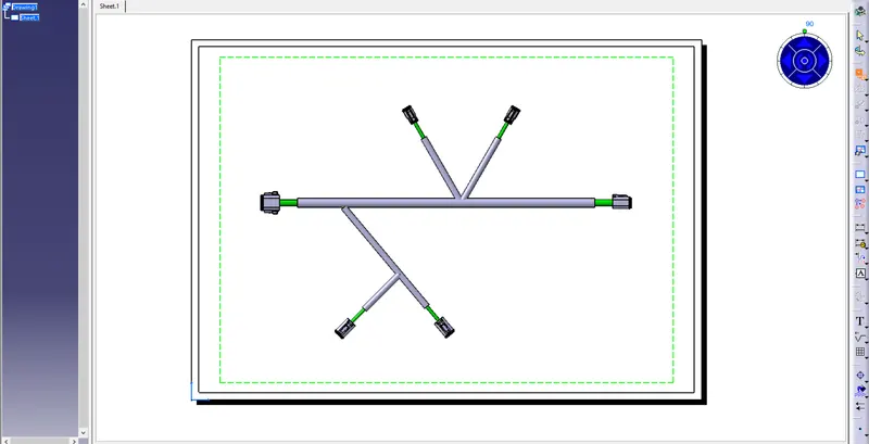
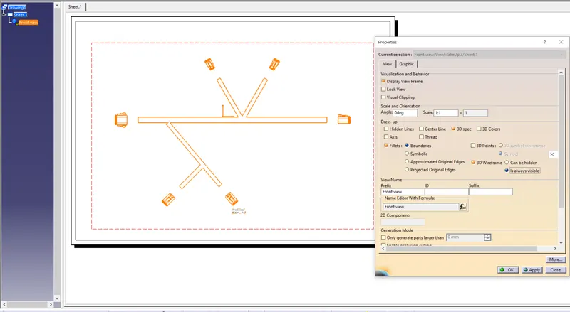
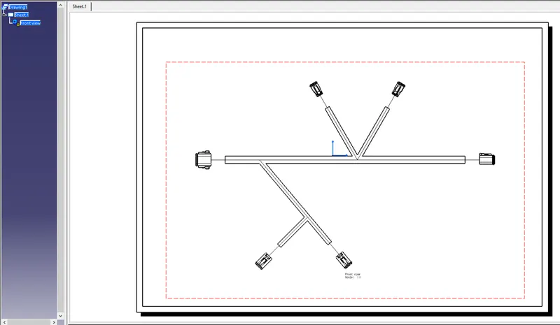
- We can see the drawing representation for the wiring harness bundle is not visible in the drawing sheet. Here, we need to change some settings in sheet properties.
- In sheet>front view properties, go to the views and dress-up area, activate the 3D wireframe and change it into always visible and click OK.
FINAL DRAWING
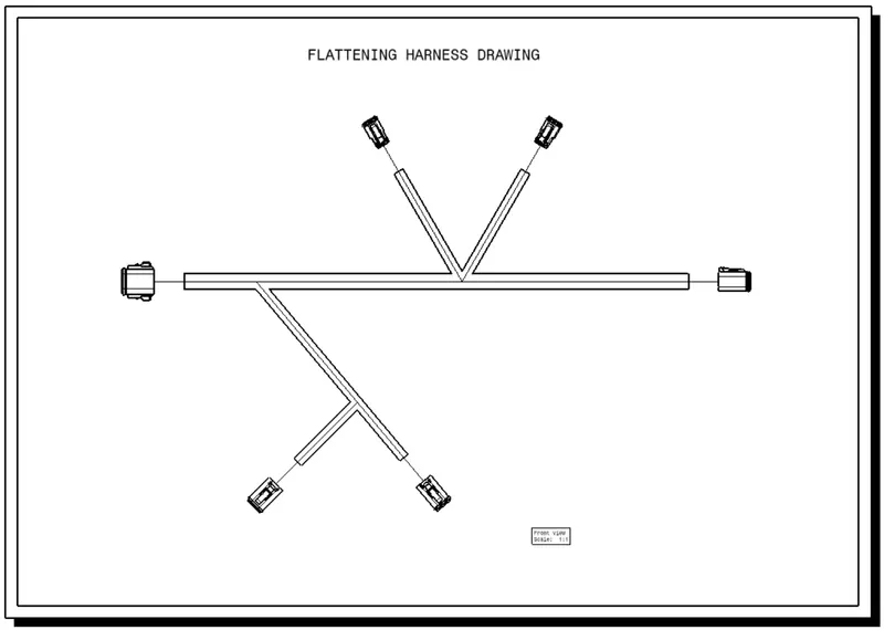
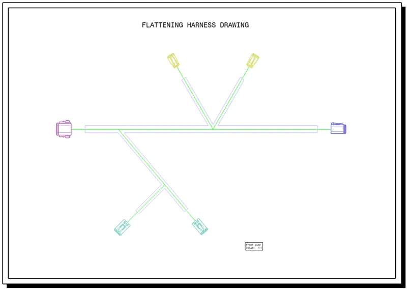
- The bundle with connector representation and different colour coding for bundle with protective covering.
Conclusion :
Final flattened drawing has been created in the drafting workbench with bundles and protective coverings having different visuals on drawing view.