Wiring harness design in CATIA V5 - 3D modeling Week 7 Challenge
WIRING HARNESS FLATTENING
Switching To The Electrical Harness Flattening Workbench:-
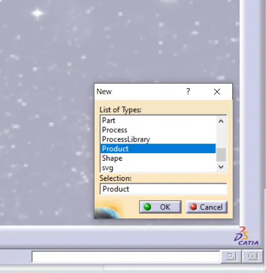
- Create New product file>>
- Switching to Electrical Harness Flattening Workbench.
- Equipment & system>>Electrical harness disicipline>>Electrical harness flattening.Then click ok.
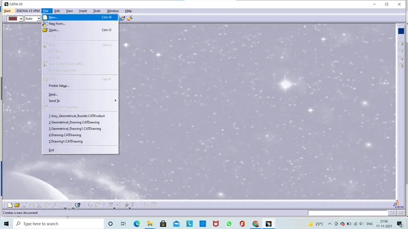
Create new product file.
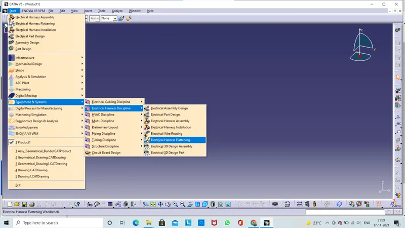
Flattening WorkBench Settings
For defining the electrical harness flattening options please follw the steps below.
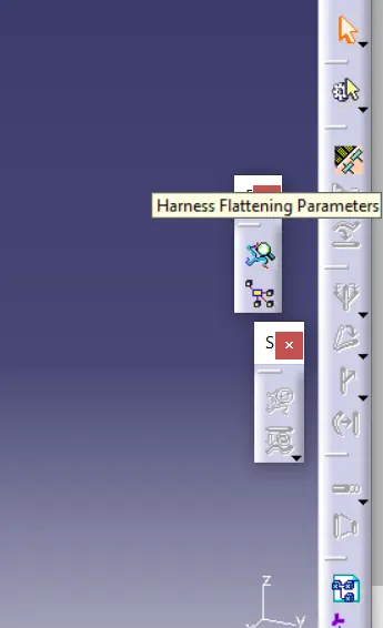
Now we can select taht the command bar is changed . Now threre is one command is activates on caommand bar except some other commands .The other commands will be active only when we define the "Harness Flattening Parameters".Those commands will be stored along with product file.
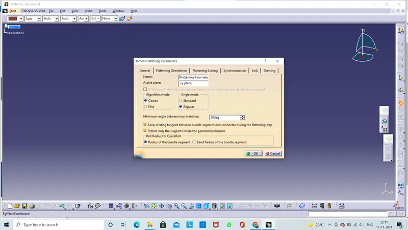
- Lets go to Flattening parameters click on this command.We can see that there is a window popup for the harness flattening parameters.
- Here asking some properties to create a flattening parameters.
- when ever we create a flattening assembly First we define the all required haeness flattening parameters.Then we work on the flattening assembly.
- Now before we import the wiring harness flattening assembly always make sure that windows in CATIA arrange vartically.Because import the wiring harness assembly into the flattening product .It should be easy accesble and easy selectable when we try to import the wiring harness assembly into flattenproduct.
- Keep it mind only two windows are open when flatten the assebly.
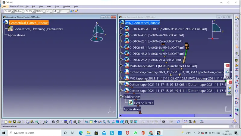
Here we using the EXTRACT command which we are use to import the wiring harness product into flattening product.
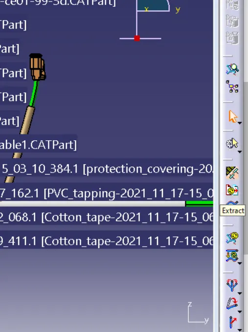
- In this process first we click on the main Flattening Product click on the extract button and now click on the another main product assembly thats has to be imported.
- Now we can see that once we import the flatten assembly into flattening product .The mian window which was open wiring assembly is now close.
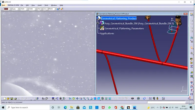
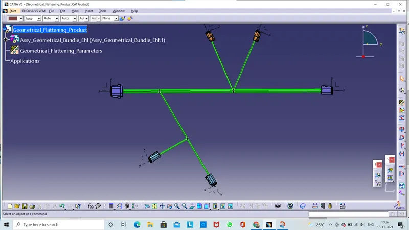
Here we see in tree representation EHF(Electrical Harness Flattening) is added that means the bundle is import successfully.
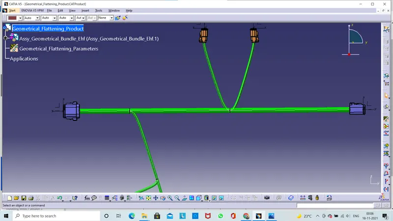
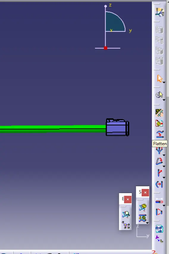
FLATTEN:-
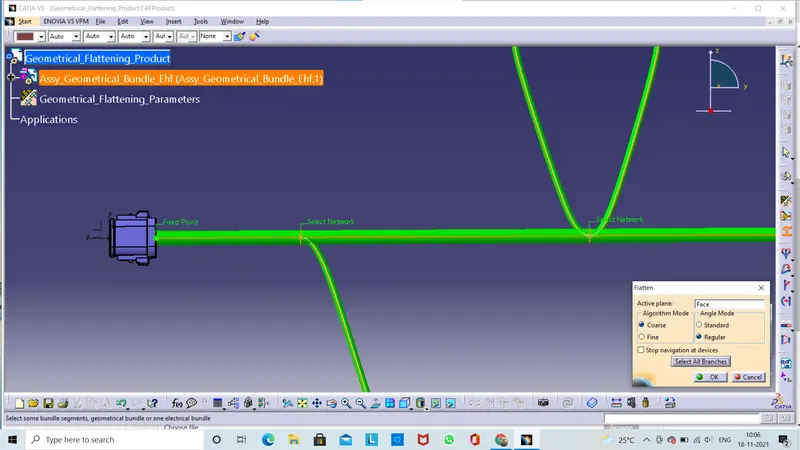
- Click on the flatten command we will have another window is popup to define the parameters for the flattening.
- In active plane we taken as default 'xy plane '. If we change the plane we can select any plane or any surface you want to keep for the flattening.
- Next step is select the braches now select all branches.Here one option is there 'select all branches' Click on this and click ok.
- Once we click on the ok button the bundel are now flatten.
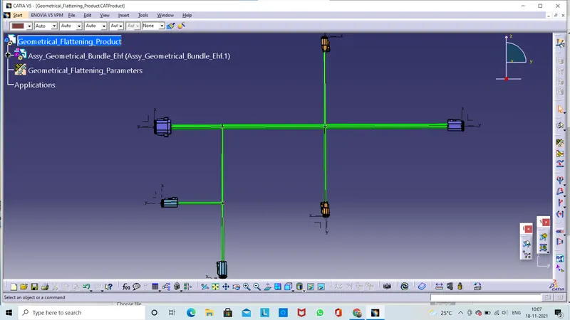
Modify Flatten Assembly:
Other commands for modifications
- Straighten>>to straighten the bundle
- Rotate>> to rotate the bundle
- Bend>>To bend the bundels. Similar to rotate, but radius is applied on bundle.
- RollL>> To roll the bundle at given point refrence.
- Quick Roll>> To roll the bundles with nearest point refrence.
- Arrange Junction - equal angle>> to provide some angle from junction point.
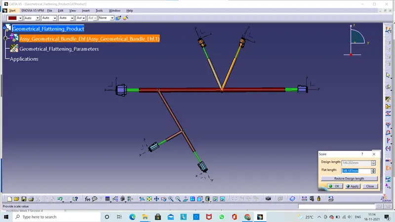
- Scale >> scaling for bundle to adjust drawing view.
- Auto update flatten link / Remove flatten link /Manually update.
- Synchronize.
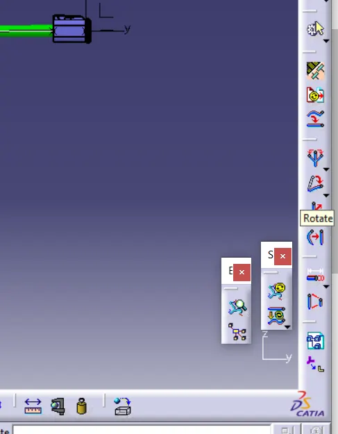
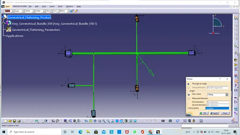
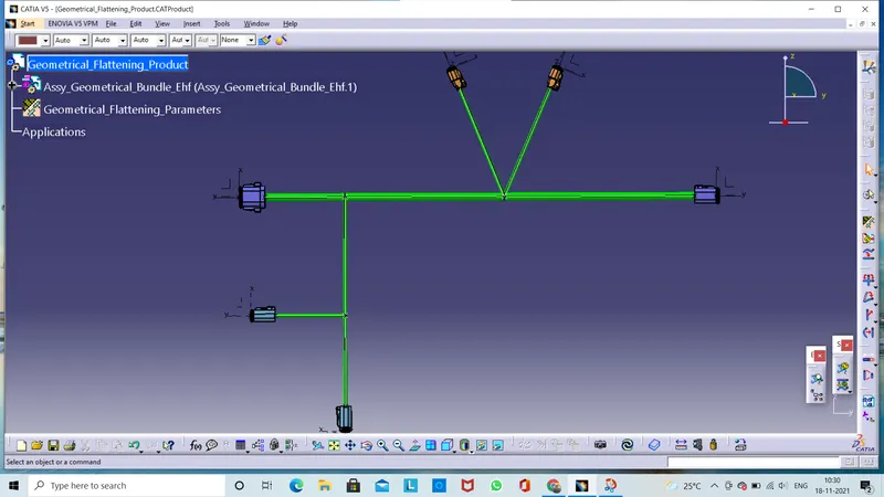
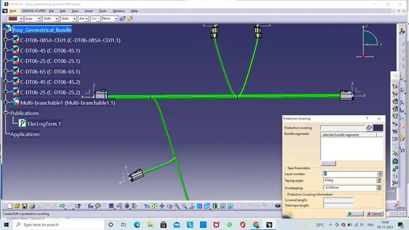
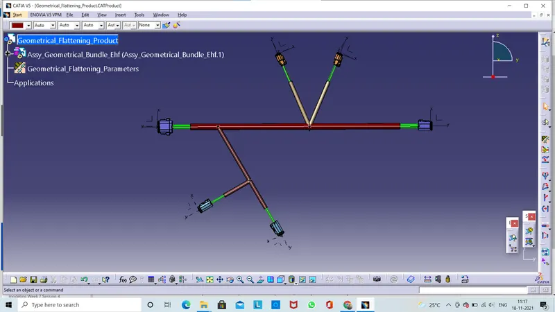
Here we adding some corrugated tubes . Click on the protection covering then apply the tapping .Those are reflected to the wiring harness flattening model.
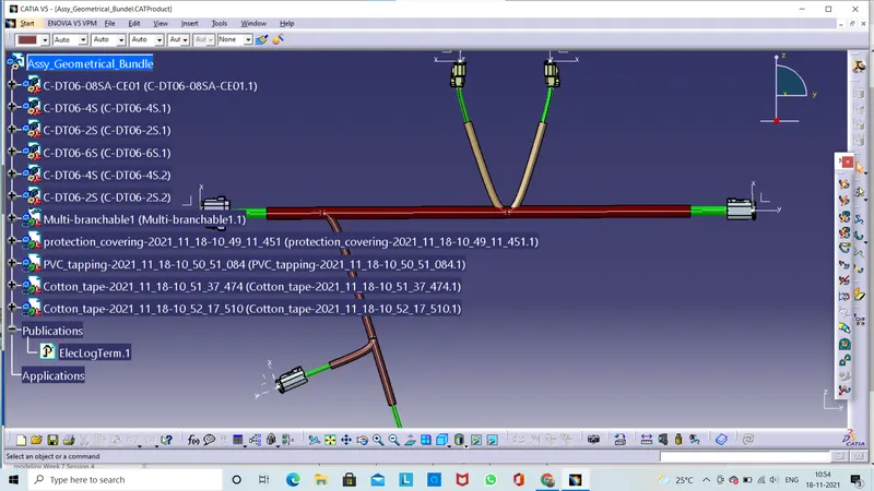
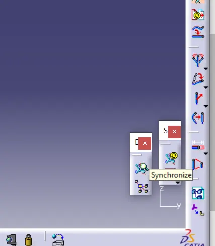
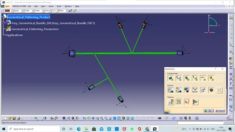
Here we use SYNCHRONIZE command click on this command another window is popup then click ok then our assembly is update then corrugated tubes are added in our assebly.
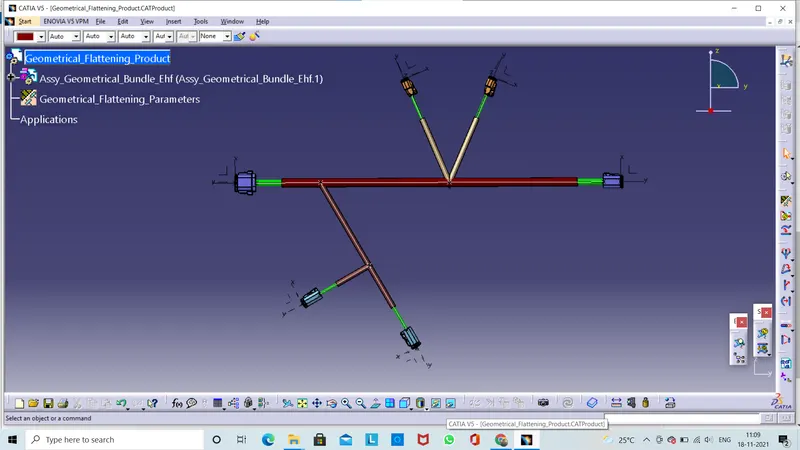
Lets click on the scale command Scaling for bundel to adjust the drawing view .
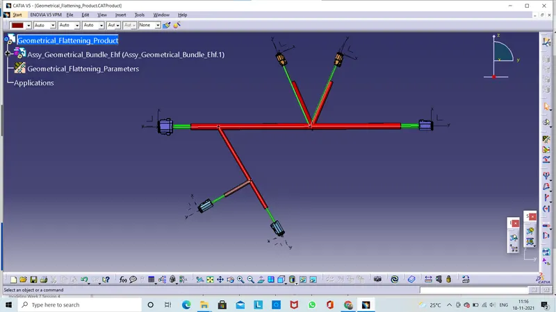
Next we click on the update button now our assembly is updated.
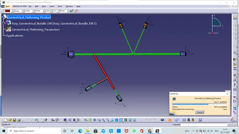
See below image the protection covering is added.And our assembly updated.
Next we go to create a 'New Wiring Harness Drawing'
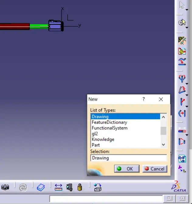
- Now go head we select the new product file.
- Click on drawing >> Click ok.
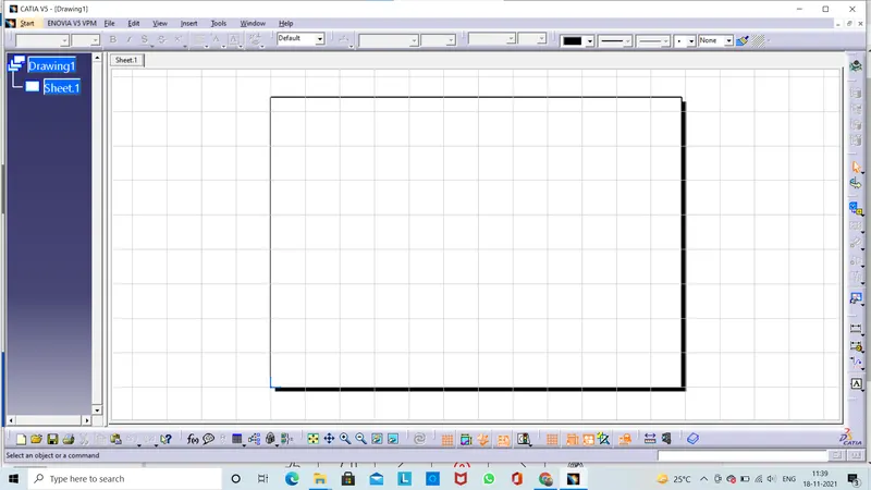
- We need to select a sheet properties to create a new drawing >>
- Click ok.
- Lets save the file.
- Here open a sheet >> then we click on front view.
- So if we need to place the wiring harness flattening view it will be always front view .Because we have to create a flatten model.So we dont need to use different views like top view, side view,buttom view..
- In this drawing creation only single view is represented which is front view.
- Lets we click on front view and lets go back to our flatten model and lets select one surface to place the flatten view.Either we can select surface or plane.
- Now my drawing view is available place on the drawing sheet.Now the flatten view can be adjusted by using right side one cricular disk is there .Then we use to rotate the flatten model.
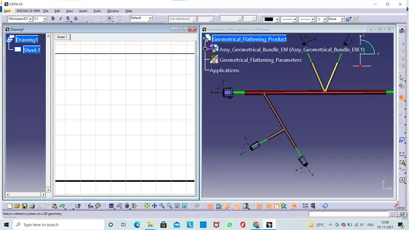
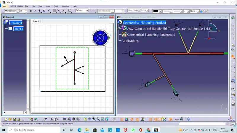
Now let`s click on the drawing sheet now we can see that here lot of information is missing .Here added some boxes,rectangular sketches are added exactly we dont know those are.
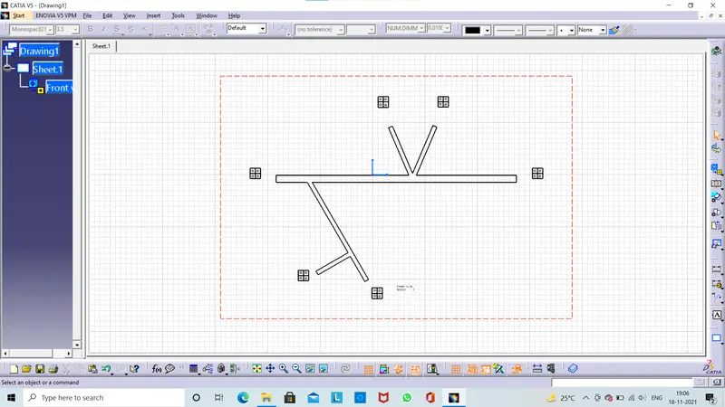
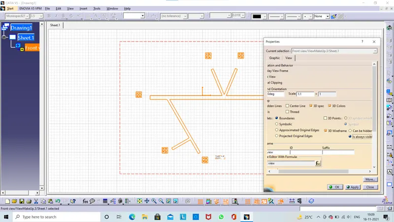
There are certain properties that has to be define into drawing view in order to get the wiring harness flatting view .Now look at those properties.Now we select the view right click and go to properties of the given sheet.There are two tapes available graphical and view properties. Now click on view properties to change the certain settings in view properties .In dress up setting we can change some properties those are 3D wireframe,3D colors then click ok.
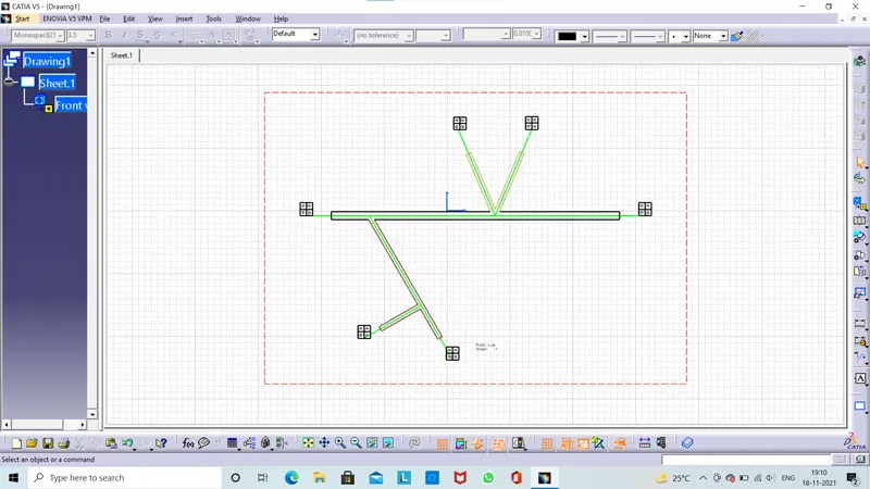
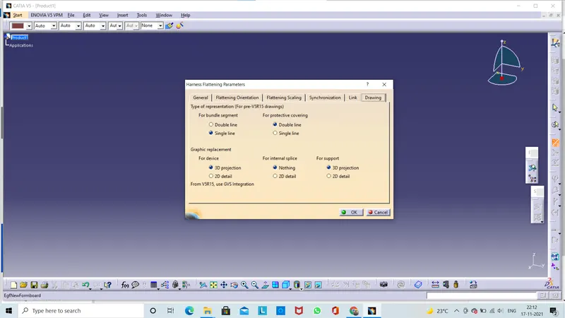
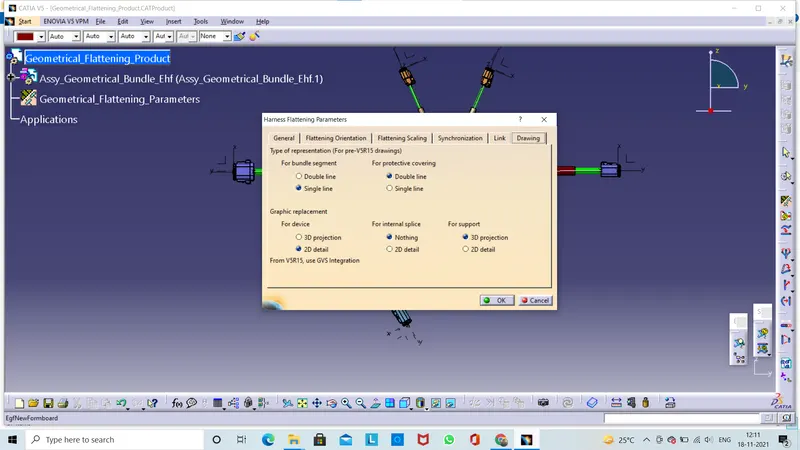
Now lets we go to flattening parameters setting in drawing window for bundle segment is we select single line and grahical requirment foe device click on 2d detali.
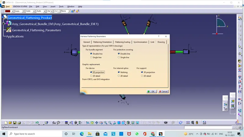
Now lets change the flattening parameters in drawing window we cam change the bundle segmeny double line and for device 3D projection.Now we see in this drawing some changes are observe.
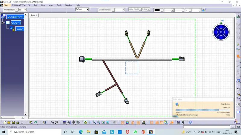
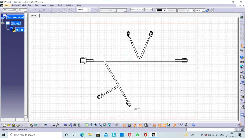
Here we need to change the some properties like 3D colors,3D wireframe then click ok.Here added diffrent colors for diffrent protection convering.Has we use in flatten model.
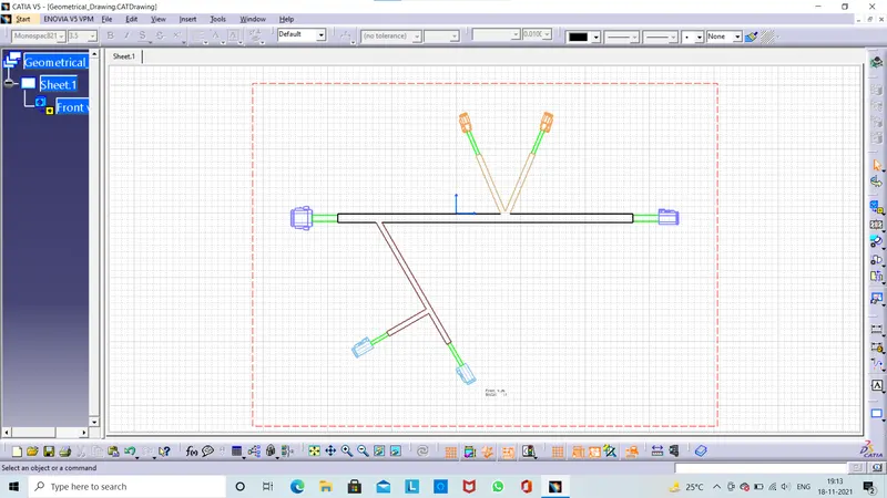
Neccessary data on harness drawings
Following data is neccessary on OEM harness drawings;
- Drawing templates and detals
- Harness layout/Line diagram or flatten drawing
- dimensions
- connector views
- Fuse& relay box view& component placement details ,lable view.
- Protection & size , location &representaion of type of protection used.
- Wire cut list
- Orientation,position of all fixing parts.
- Generic notes for specifications of devices.
- All these data is not driven by CATIA EHI Module,ECAD interface helps to create details driven by circuits. Manually data entry is used by few OEMs due to budget.