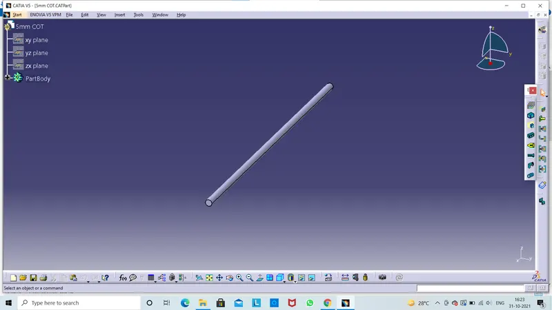
Wiring harness routing & packaging Rules Week 3 Challenge
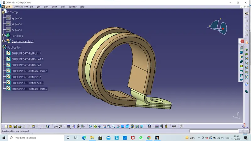
WHAT ARE THE IMPORTANT PARAMETERS REQURIED TO BE DEFINE A"P CLAMP" AS A ELECTRICAL SUPPORT.
Clip Defination:-
This another important component of the wiring harness which should be define wiring harness routing following important parameters requried to define.
- Entry Point & Plane
- Exit Plane
- Base Plane
Clip has two entry points and two exits points,
For example the wire can be inserted left to right and right to left . It's bidirectional that's why in this case we define support defination two times.
Define "Geometry Parameters":-
First get the P Clamp 3d part ,we switch into part design workbench and we click point defination icon to a entry point and exit point .Next we create the plane for entry and exits planes for early created points and also create base plane.
Point Defination icon use to create a mid point(entry point) of p clamp .
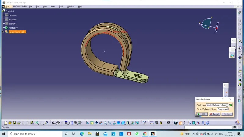
Next we can create the exit point of given p clamp part.
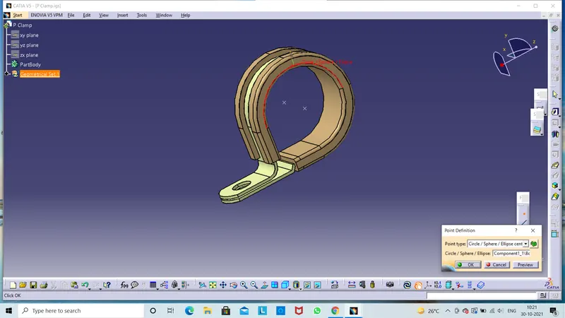
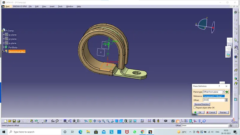
Next we create plane for that is entry plane click ok.
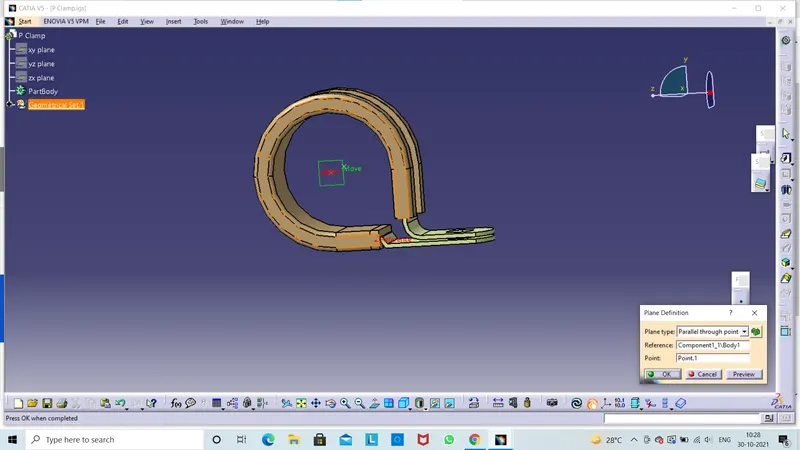
And same way we can create the exit plane click ok.
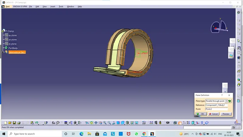
And last we create base plane click ok and save them.
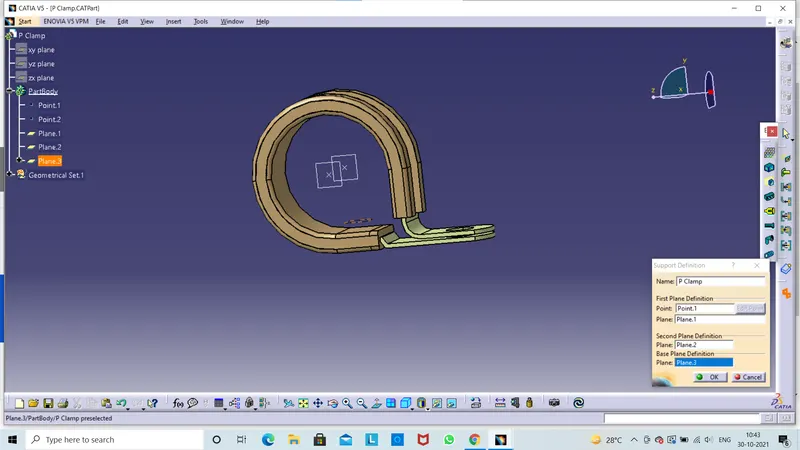
Define as" Electrical Support"
Go to Electrical Part Design workbench.
Click on "Define Support Part"
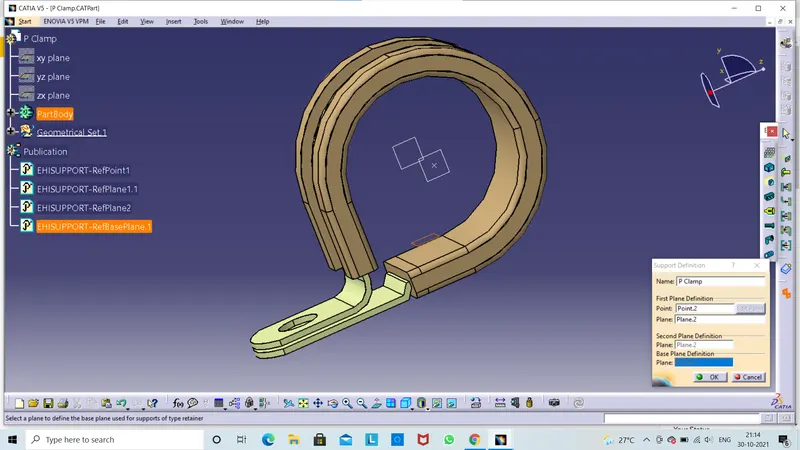
Here separate window will be displayed in name we can change the name or by use the default name .In 1st plane defination then select the 1st point &1st plane .We go second plane defination.Then we select 2nd and base plane.In this defination two entrys and two exits are available then we create two sides of the part.Then our clip is ready for wiring harness assembly.We don't need to see the plane then we can hide them and let's save them.
Q2) WHAT ARE THE IMPORTANT PARAMETERS REQURIED TO BE DEFINE (Tyco 1738312-1)BACK SHELL:
Define Back Shell:
- Back shell are plastic model part used at wire side of connectors either for protection or to improve aestheties/appearance of harness.
- These are not mandatory part of wiring harness .Are always optional and driven by cost.
Define Geometry Parameters:
- Methodology and logic to define the point &axis system is as connector connection system.
- Ensure that defined axis & orientation should be identical with mating part.
Click on point defination then we create a mid point .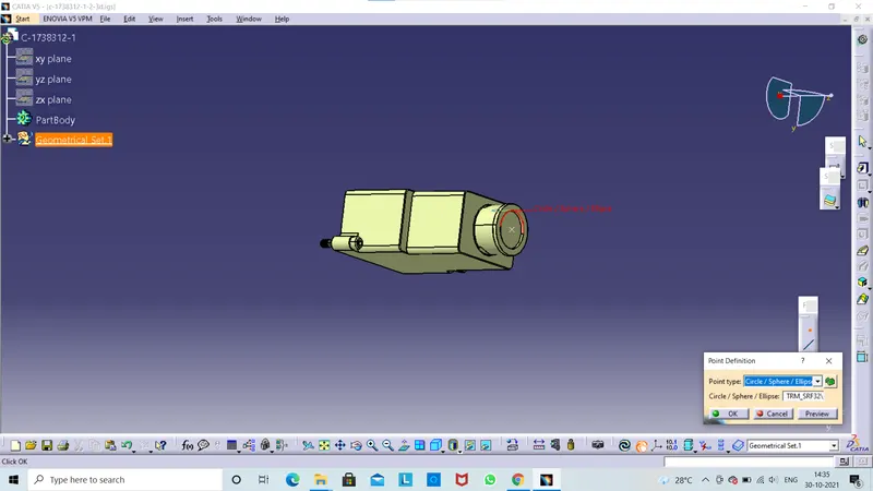
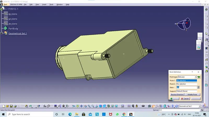
Next we click on Axis System defination here separate window will be appeared.It wii ask some properties for points and coordinates system.
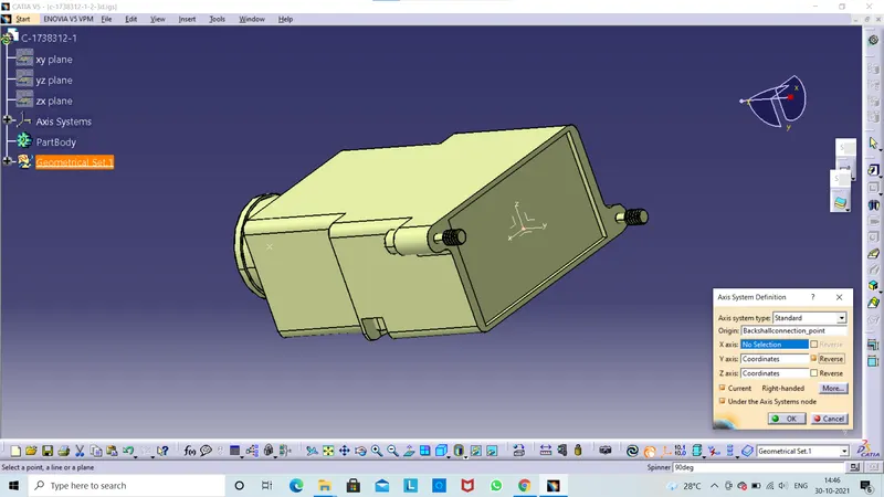
Back Shell Defination:-
Go to Electrical Part Design workbench.
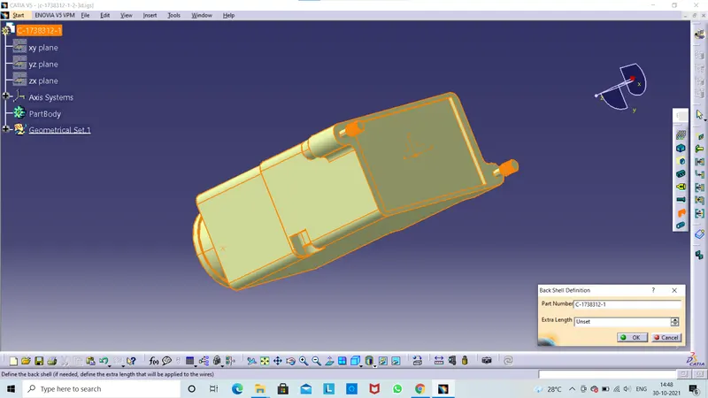
Click on Back Shell Defination icon .Then we click on the 3d part.Here separate window will be appeared.It will ask for the part number and extra length then click ok.
Define Back Shell Connection Point:-
We select the define backshell connection point command .Then click on the part . Here separate window will be appered.It will ask some properties for back shell connection point.Click ok and save them.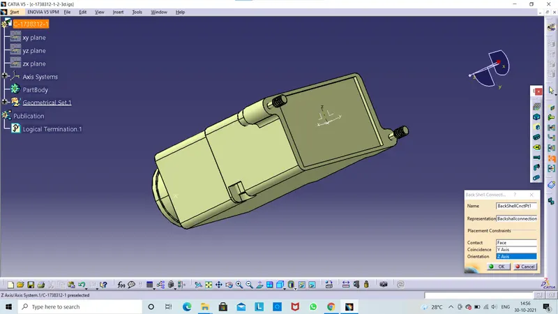
Define Bundle Connection Point:-
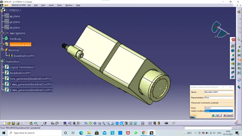
Click on define bundle connection point command click on the part .Here separate window will be shown.It will ask name ,representation ,point and initial condition then we can fill.
Q3) Create Some Corrugated tubes & Add them in Catalogue under “Slit COT” family.
Protection Covering:-
- Corrugated tubes , convolutes, sleeves,and many other types of covering are uesd to protect the wiring harness.
- Graphical representation of covering are applied on bundles
- Create the covering 3d part.
- Create catalogue for coverings.
- Add new part in catalogue Apply covering on harness bundle from catalogue
Create Protection Covering:-
Go to Electrical Part Design
- Click ok define 'Protection Conerings'
- Click on part body from model tree.
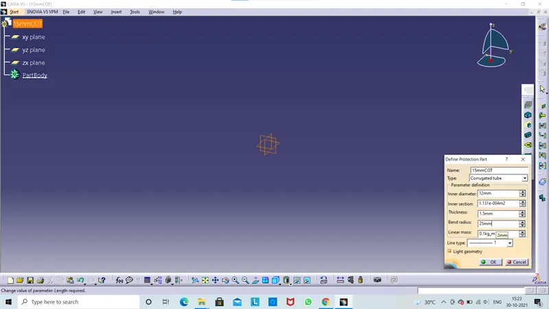
- Enter part name as "15mmCOT"
- Select the type as Corrugated Tubes.
- Enter parameters like...
In our question inner diameter for 15mmCOT Tube is 12mm.
The inner section automaticaly calculated by the inner diameter it shows in mm2
In thickness we can enter 1.5 mm
Now Bend Radius is most important for wiring harness routing process.Generally bend radius is 1.5 times of external diameters.
Next Linear Mass also calculated by enter those parameters its shows weight.
Next select the line type.Click ok.
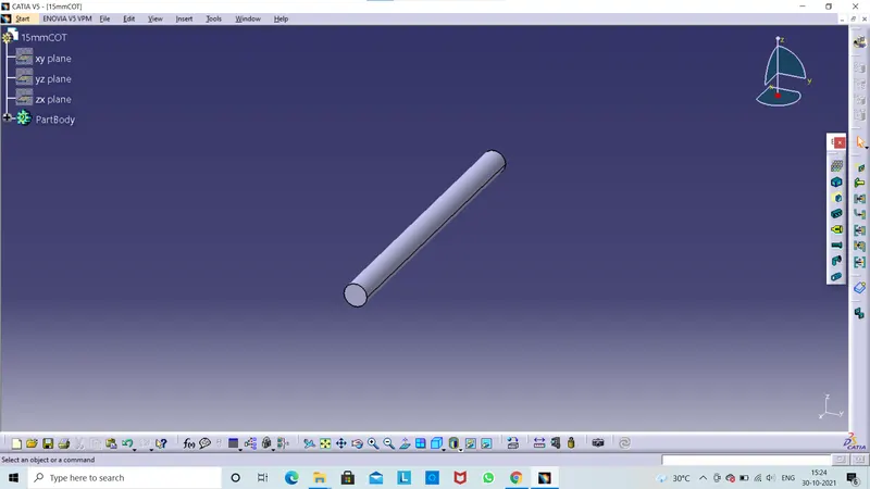
Create Catalogue For Coverings:-
- Click on add family icon
- Then enter family name as "Slit COT",Then select 'Conduit, then click ok.
- Save the catalogue family and close it.
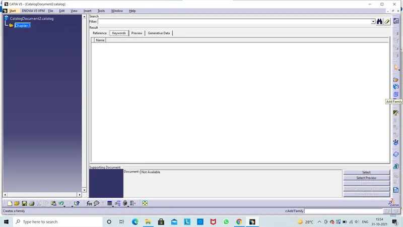
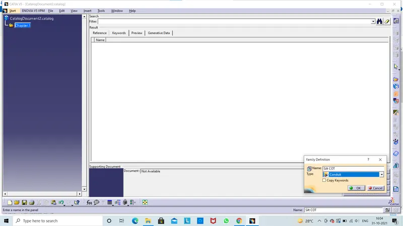
Add new part in catalogue:-
Go to Electrical part design
Open created 15mmCOT tube .CATPart file.
Click on store device icon
Browse &select created catalogue.
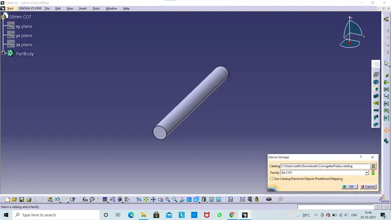
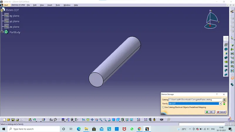
Select family as 'Silt COT',Then ok.
Now created 15mmCOT tube is added in catalogue.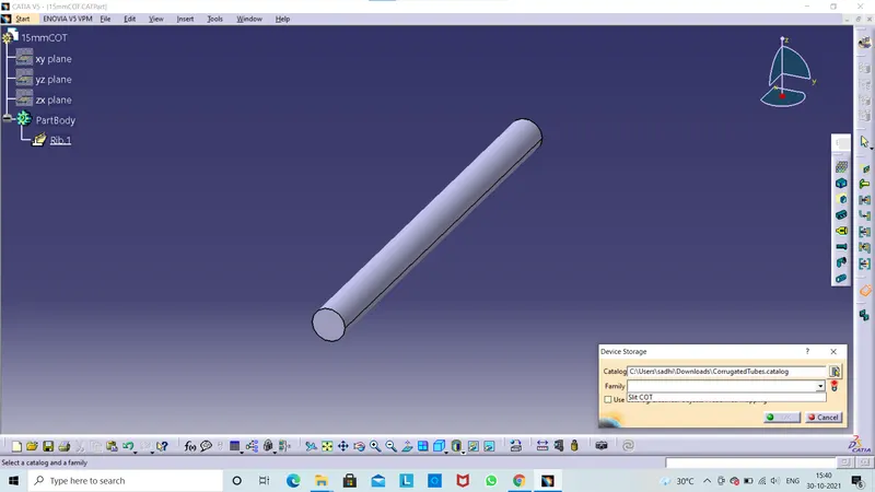
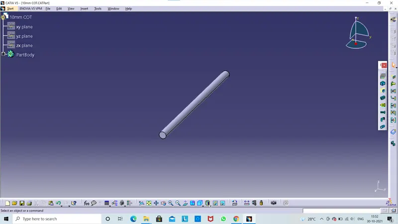
Follow the same procedure for create corrugated tubes & add them in catalohue under 'Silt COT' family.
20mmCOT
35mmCOT
10mmCOT
5mmCOT