Wiring harness design in CATIA V5 - 3D modeling Week 2 Challlenge
Wiring harness design in CATIA V5 - 3D modeling
First we can open te.com site download the Deutsch DT06 – 08SA and open in CATIA V5 software then we define connector defination.The following parameters are requried to define for any connector .
STEP:1
Geometry Parameters:- Points and co-ordination system (axis system).
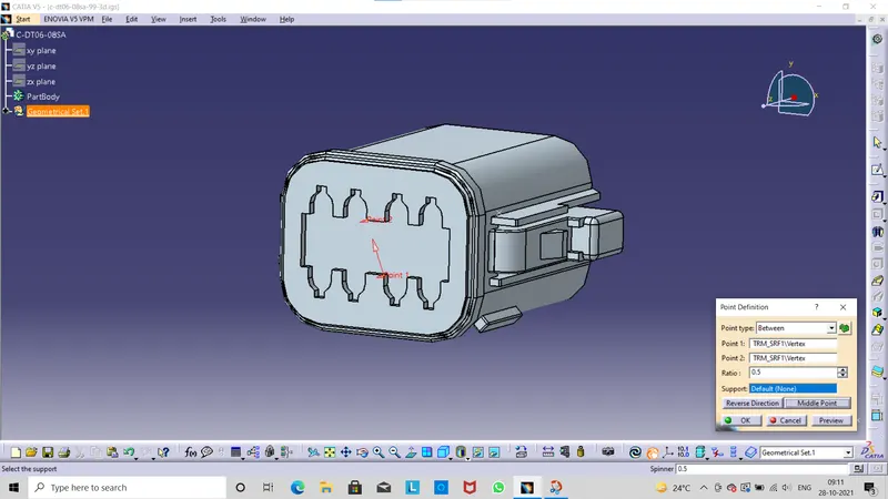
We can work on part design in this workbench we define point defination then click on point definaion command.
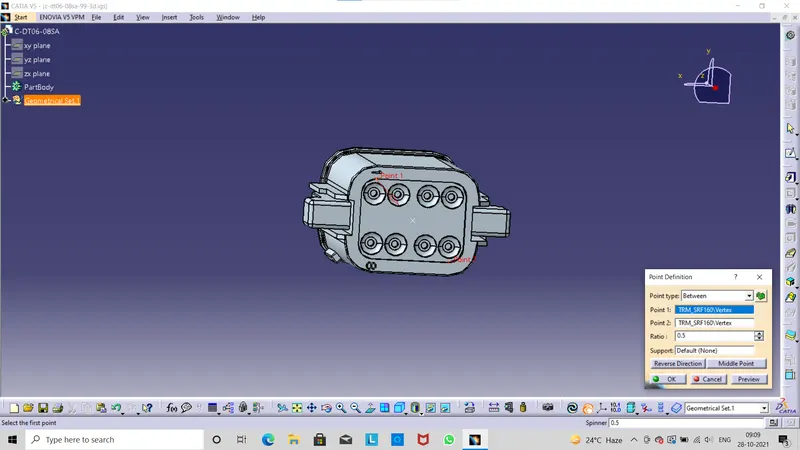
we use this defination can finding the exact center point of the connector.In this selection process we choose two points then find the exact mid point .We create both sides of the connector.
STEP:2
Axis System Defination used to define the co-ordinates system .we can select the origin exact the mid point.
X-axis should be pointing in the direction towards the locking mechanismof the clip.
Y-axis should be pointing towards the front face of the connector.
Z-axis should be pointing across the connector from left to right.Then click OK.
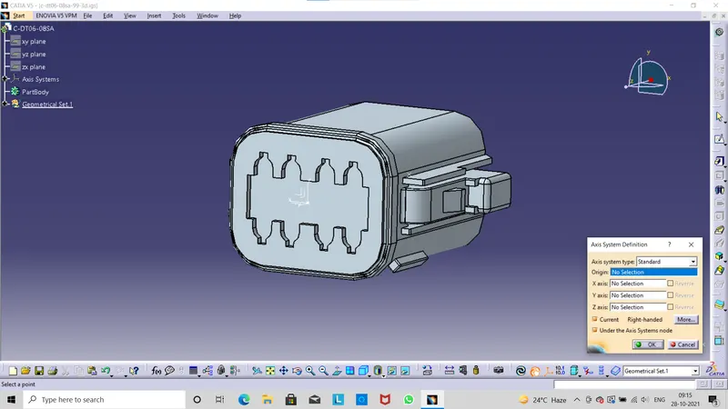
STEP:3
Next we jump into Electrical Part Design workbench can we define to connector defination. Then click on the command it shows from the below fig.Here asking type we can enter single insert connector,part number taken default and last number of terminals we can enter 8 in this part design we can see and observe its a 8 therminals are there .
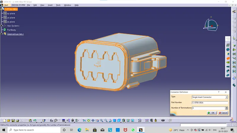
STEP:4
Next we go for Bundle Connection Point Defination click on this command the window will be display as shown in the below fig .Here asking some properties for define the bundle connection point. Then click OK.
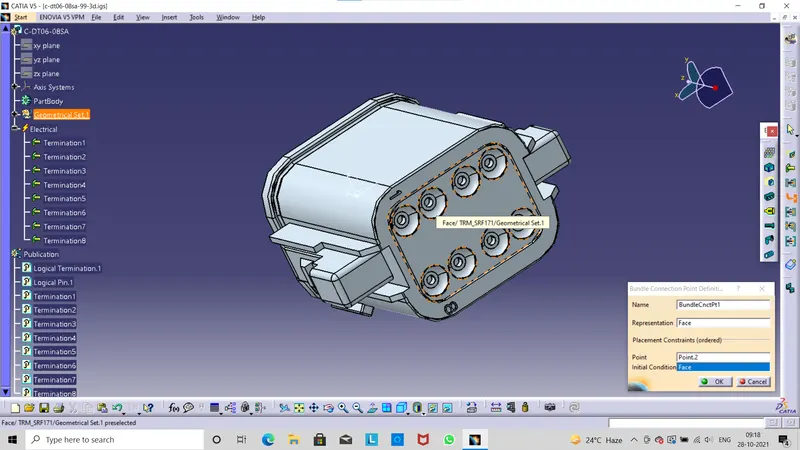
STEP:5
Connector Connection Point this point is used for connection of one connector to another connector.Then we click on this command the below window will be display here asking some important properties.Representaion we can select the axis origin, contact can select the normal to the face,coincidence we can select the always y axis , orientation can select the always x axis direction.Then click ok then save.
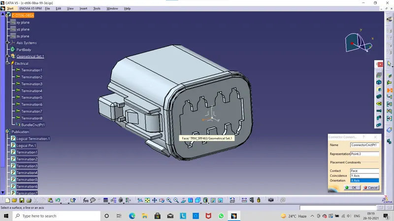
STEP:6
Then click Device Storage command open then we can select the catalog for connector then open it and select the family here shows connector then select and click ok.
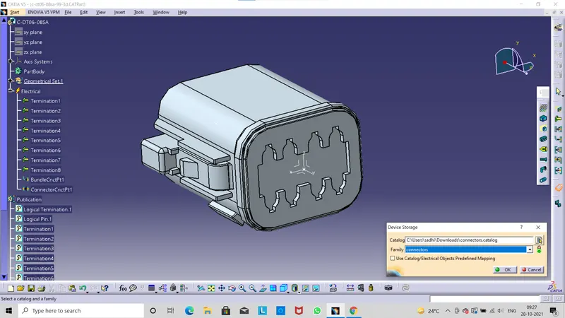
Next we can download the another connector from te.com and we can search in search bar Tyco 174357-2 .Then downlod the CAD part.Open the part in catia v5 then define the connector defination .
The following parameters are requried to define for any connection
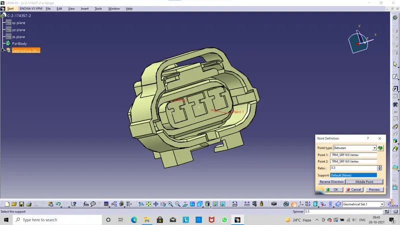
Geometry parameters:- Points and co-ordinate system that is axis system .We define point defination first for both sides bundle entry point and connector connection point .
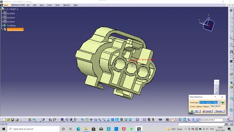
.
Axis System Defination can use to define the axis system and co-ordinates
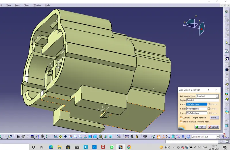
The connector axis system should be on front face of the connetor attached to a point on 0,0,0 co-ordinates.This points should be in the centre of front face as this point will be used to connect the connector to another electrical component.select the create an axis icon from the workbench.
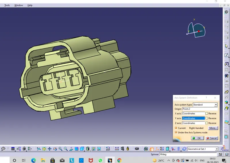
Next we can also define axis system for aother side because of the cavity connection then define the axis system to the locking side of the connector.
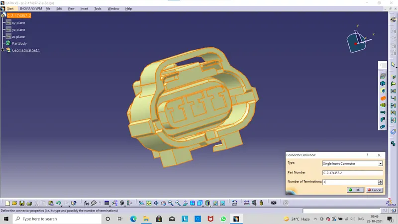
Next we jump into Electrical Part Design icon from the workbench
we go to connector defination can enter type of connector its a single insert connector and part number is taken defalut, and next we enter number of terminals we can enter 3 we see in this 3d model here three terminals are there then we can entet three.
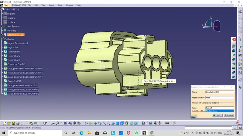
Next we can click on Bundel Entry Point icon this point defines where the harness is bundle segment point will end when route to the electical connector.
Click on Connector Connection Point icon this point is used for the connection of one connetor to another connector.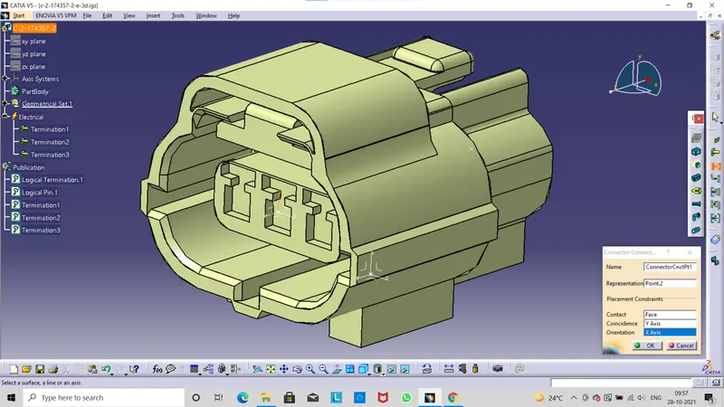
Next we click on the Cavity Connection Point icon this is used to define the connection of a connector to a connector cllip .This only applies to connectors which have mounting feature for a connector cllip .Then we can save in .catpart file.
T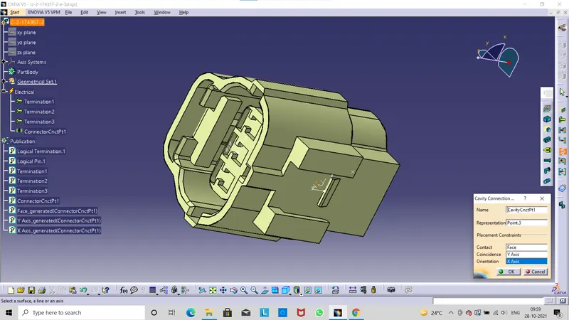
Next we can download the connector clip (Tyco 85229-1) from te.com
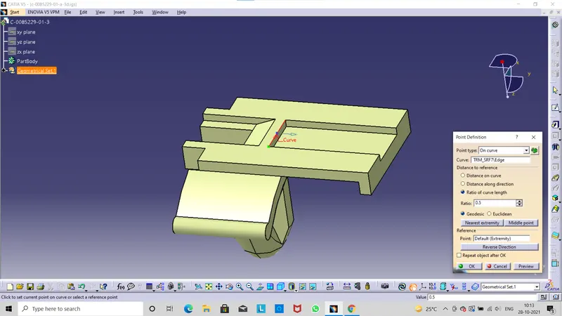
we define the point defination and create a point.
.
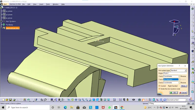
Next we go to Axis System Defination icon then define the coordinates on axis system.
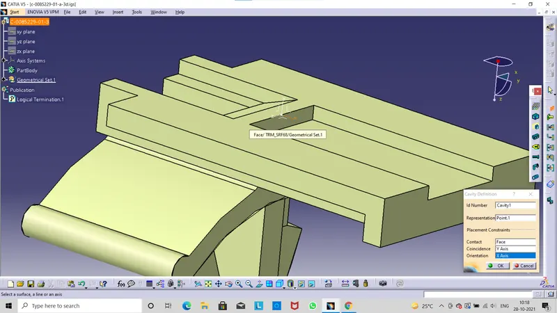
Select the Cavity Defination icon from the workbench this similar to connector connection point only change the icon then click ok and save.
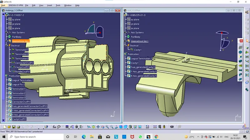
Create new product file then copy those two 3d models and past it on newly created product file.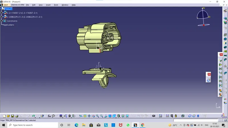
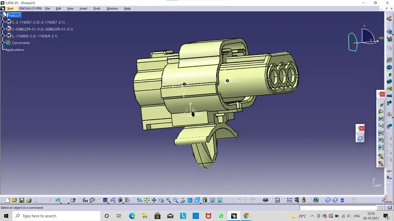
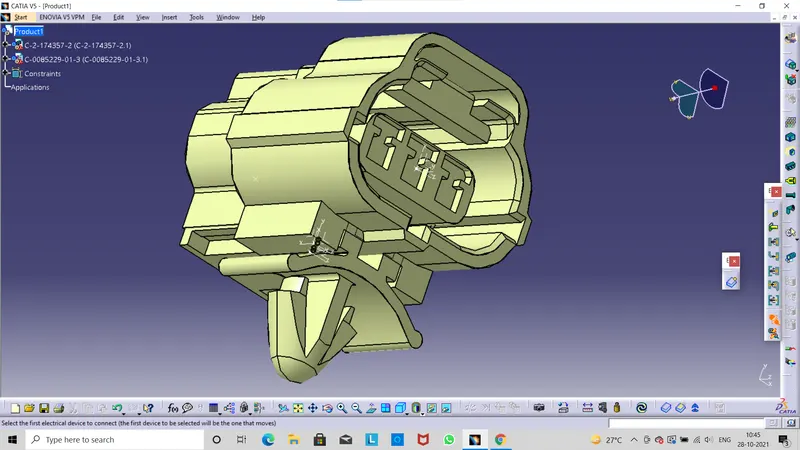
Next we change the workbench in start menu click here Equipment & system here sub option are there we can select the Electrical Harness discipline next we go for Electrical Assembly Design.Then the workbench is changed.Here connect electric device icon is displayed then click on this command then can assemble the two parts click on save .
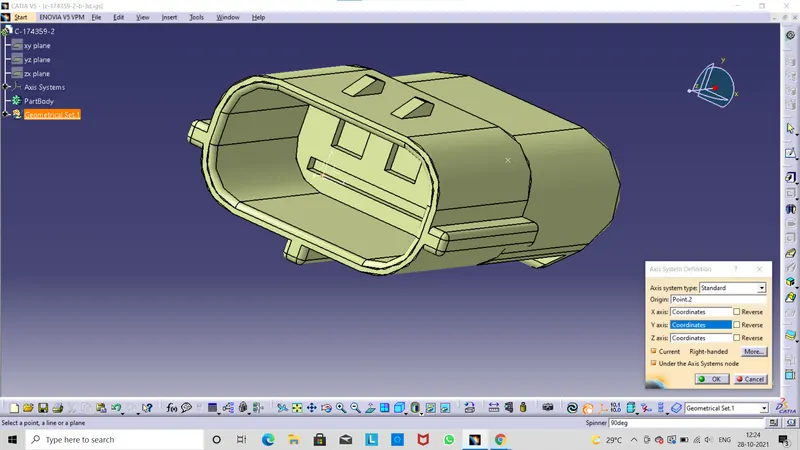
Next we download the male connector (174359-2)from te.com for connection of female connector (174357-2).Then we create a point defination click ok.
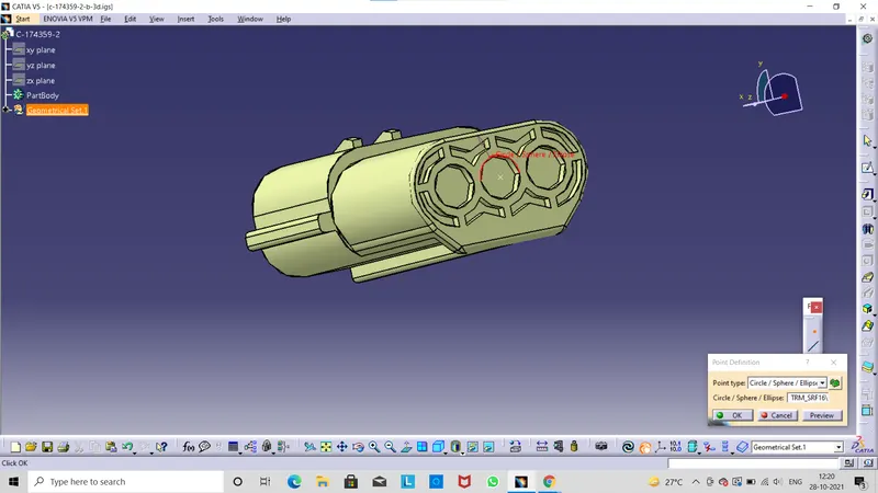
Axis system defination we define the coordinates and axis system then click ok.