Wiring harness design in CATIA V5 - 3D modeling Week 5 & 6 Challenge
Creating the Wire Harness Geometrical Bundle
Harness Bundle creation for given Harness Layout(Harness_A):-
Follow below steps to create geometrical bundle /harness assembly
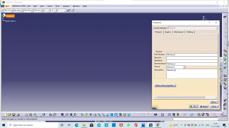
- Create New Product File .First we can click on file next select the New and last select product
- Again change the product part number to" Harness_A".
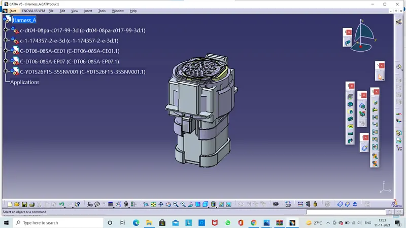
- When creating the wire harness bundle segment you are first required to insert the electrical components thats you need route the wire harness from and to.
- Before you can route the wire harness you will need an electrical defined.
- This data should be also be removed from your context assembly before saving.
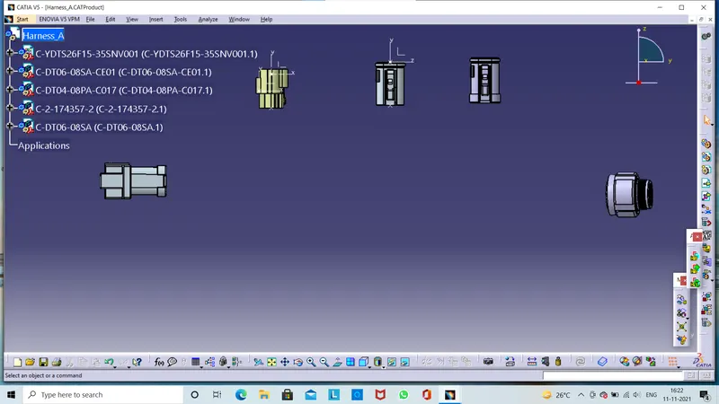
- There are five main function for moving and positioning the electrical wire harness components.Those are in assembly design workbench.
1) Mnipulation.
2) Translation & Rotaion
3) Snap
4) Smart Move
5) Compass
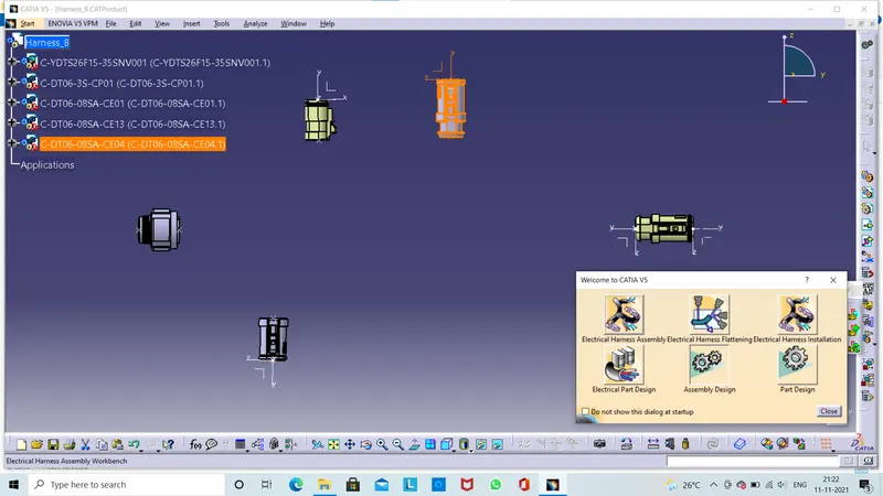
- Switch to Electrical Harness Assembly Workbench icon.
- Then select Geometrical Bundel iocn. Then select product from model tree(what we are created) product icon in model tree is changed now and name changed "Geometrical Bundel"
- Our assembly is changed from mechanical assembly into electrical assembly.
- Next we click on bundel defination the multi branchable and publications are added to our assembly.
- You must now place each electrical part into its correct positioning the your geometrical bundle production file.
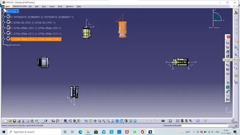
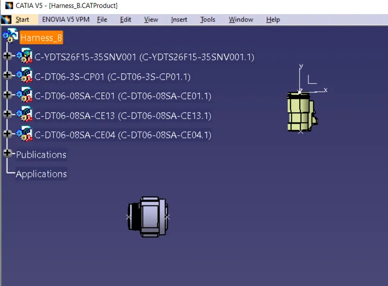
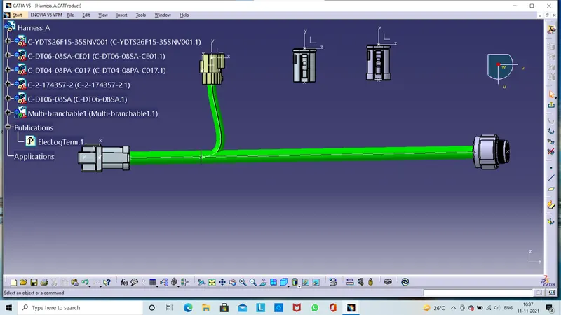
Then our assembly is converted mechanical into electrical assembly.Next we click on the Multi-Branchable Document Then we can route the bundle.
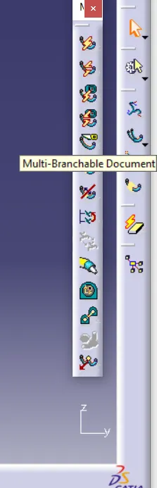
Then we click one bundel defination here we enter diameter is 15mm and bend ratio is 1.4 next click on slack parcentage is 0 .Then click route defination here we can select the first connector and click add after then select the another connector then click on reverse tangent and click ok.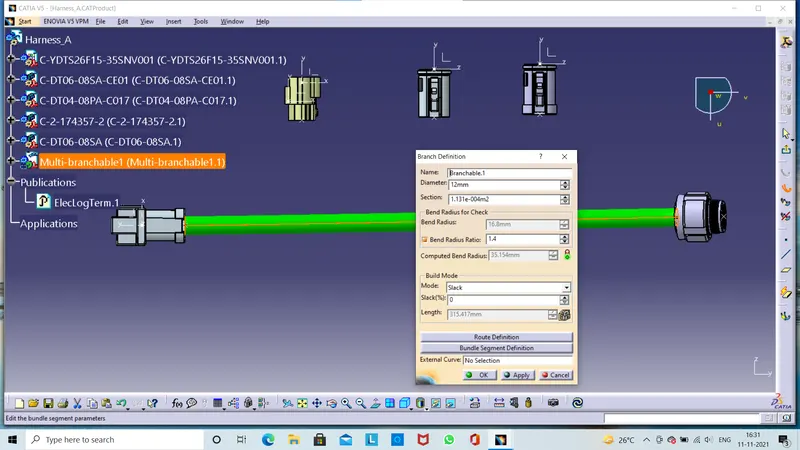
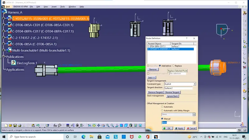
Next step click on Add Brach Point then we select the at what distance to create the brach point in main branch.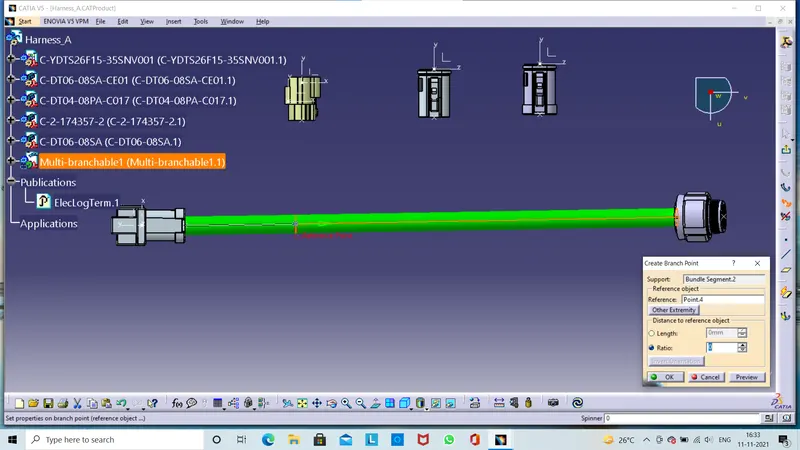
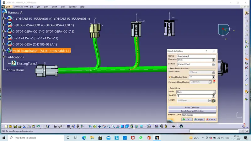
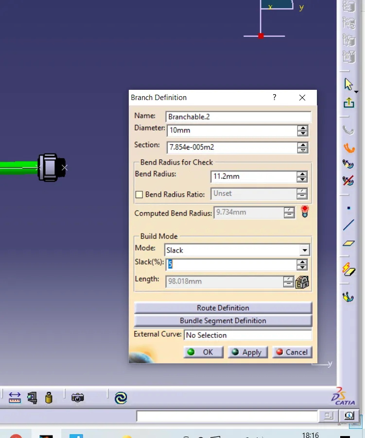
Then we click on brach defination then we can click in diameter 10mm click route defination .Here showing some error in bundle creation the computed bend radius is less than bend radius thats why we are adding 5 % slack then resolve the problem.
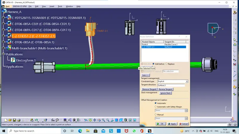
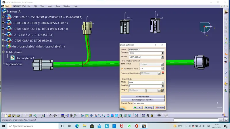
Same process for another connector first we click branch point and route defination.Here also yellow warrnig is displayed on multi brnchable tree icon then resolve the problem we can add the some slack% or some time to change the connector placement.
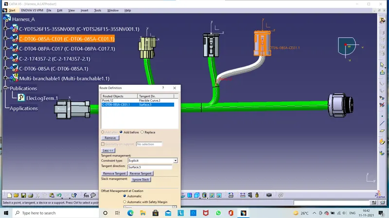
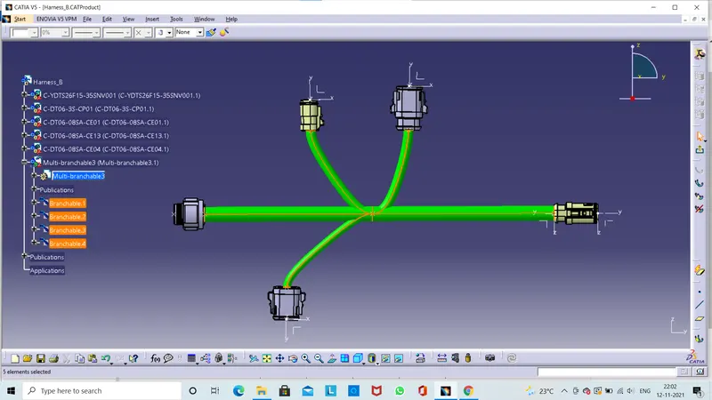
Our wiring harness assembly is done then we click to update and lets save it.
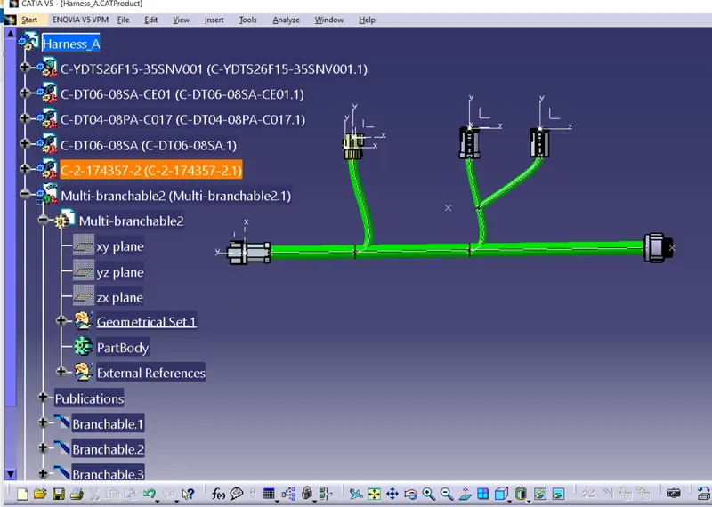
1.Bundle Continuity Check /Analysis:-
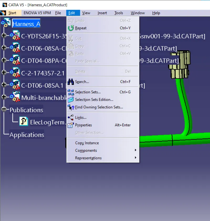
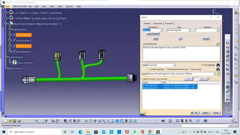
- To check the bundle continuity go to edit button click on search .Here new window will be displayed .Then we click on advanced.
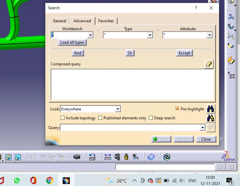
- Here asking some properties like workbench,type and Attribute.
- In advance workbench select the electical ,in type we need to check the bundle segment continuity and attribute we need to check the fully connected .
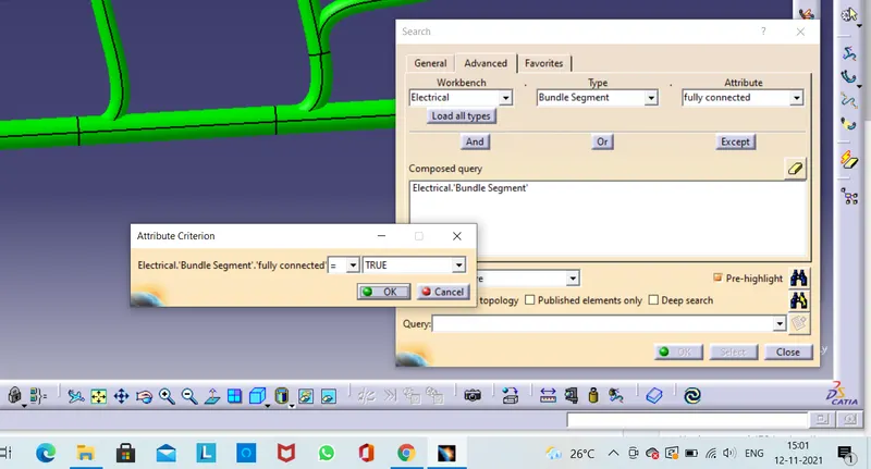
Here another window is pop up that is attribute criterion .Here we can find out the which bundle segment are connected to gether .Then we can select the TRUE.Then click on ok and click on search.
The select the branches are connected together.
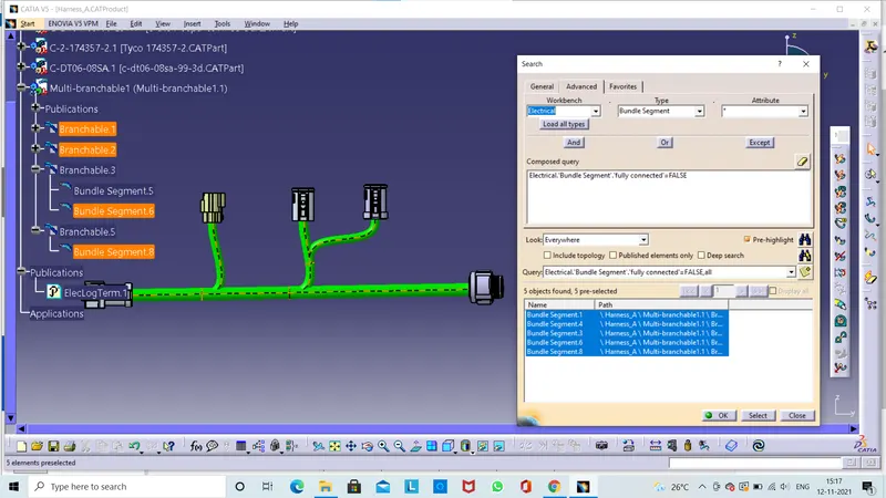
Next we can select the which bundle segment are not connected then we can select the FALSE.Then we click on ok and click on search.
.
Then we can check those bundle segments are not connected then find out the problem and resolve it and check it once the bundle continuity .The selected bundle segments are connected together. 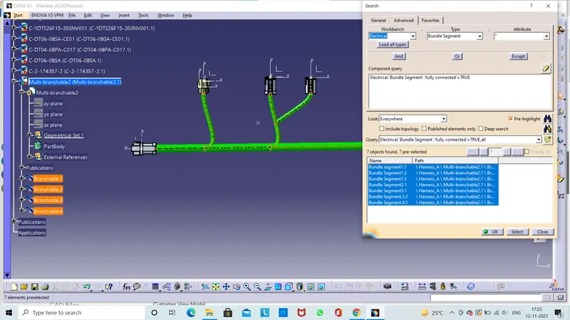
And once again to check the bundel segments are not connected together in statement we can select the FALSE then click ok and click on search.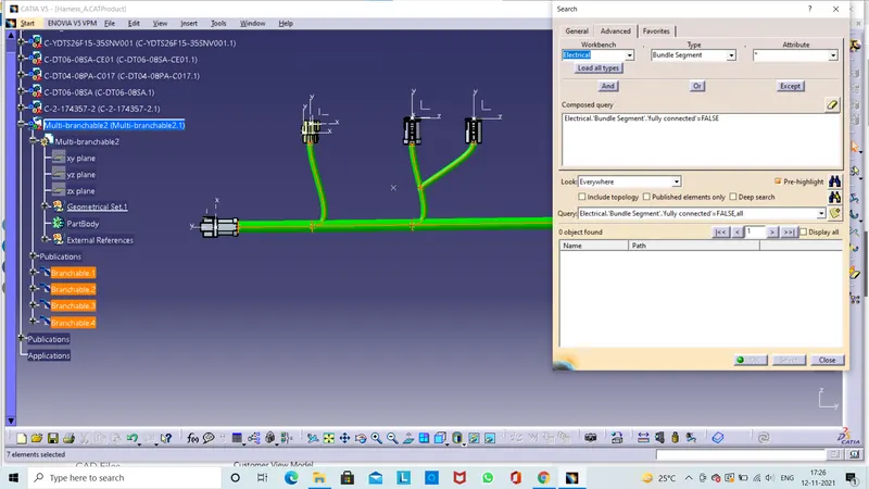
2.Add annotation to all connectors.
The 3D Annotation is used on the wiring harness to show the connector functions and additional notes.
Connector function annotation :-
This annotation is to be added to the connector to show the function of the connector /unit it is connecting to .This is use full for other design departments who requrie the 3d harness models but are not familiar with the harness connrctor function.
Creating the Annotation:-
- Switch to the assembly design workbench.
- Make sure the geometrical bundle is active.
- Select the front view/annotation plane icon.
- Select the plane you wish to use for the annotation .
- Select the flag note with lader icon.
- Select a reference point on the part you wish to add the annotation to.
- Input the connector function (unit name)in the name difination select ok.
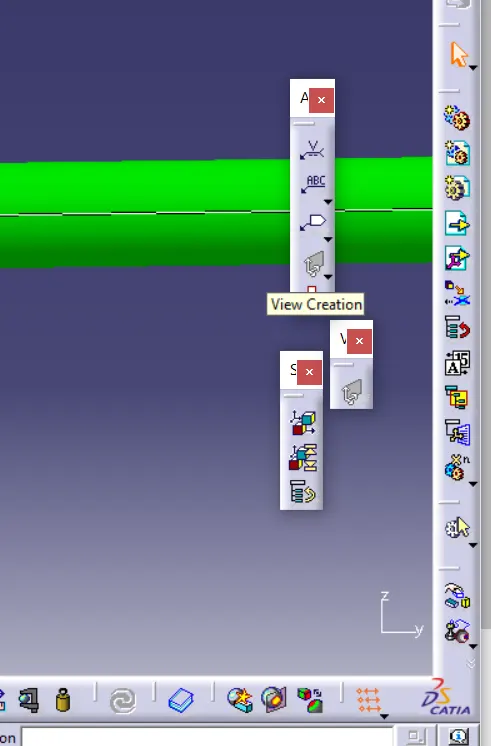
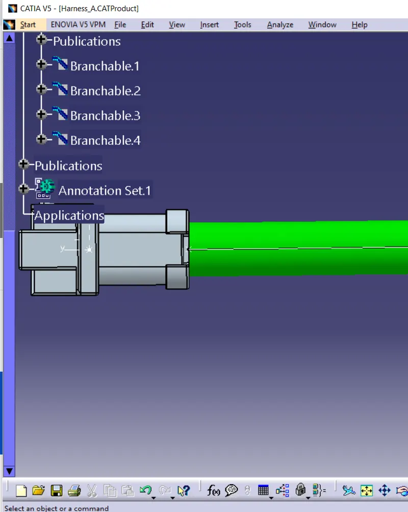
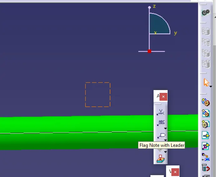
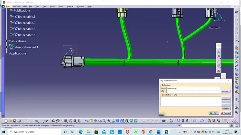
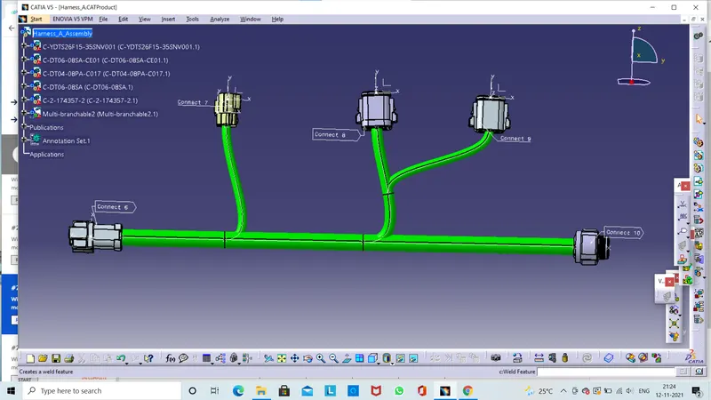
The 3d annotations are created by using the flag note Defination here we can enter connect 6,7,8,9,10. We can enter what we want .
3. Check for the bundle warning:-
It is possible to get warnings when routing our wire harness.These warnings are usaually displayed in the tree strcture of t5he wire harness geometrical bundle.These warnings are usaually related to the bend radius,bundle diameter or vector position of our bundle segments,if these are any issues with the above then a yellow flash warninig symbol will appear in the tree strcture of the geometrical bundle.
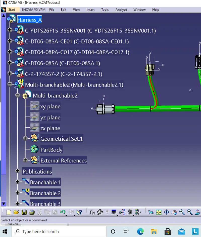
To reslove the problem we can add some percentage of slack then it will not working next we try to replace our connector . Another option is change the diameter of the bundle segment.The main important point is to check the computed bend radius always greater than bend radius.
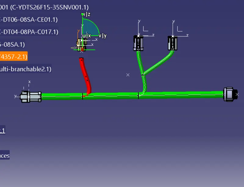
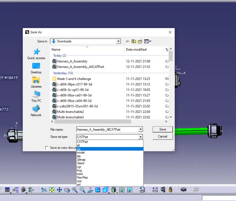
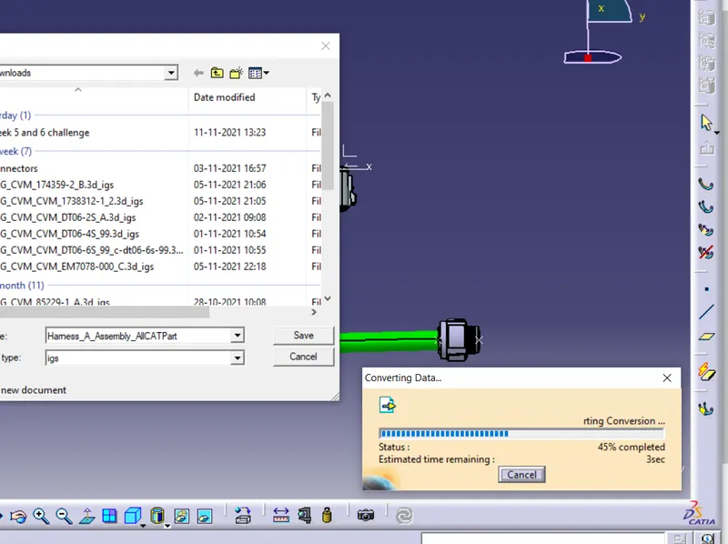
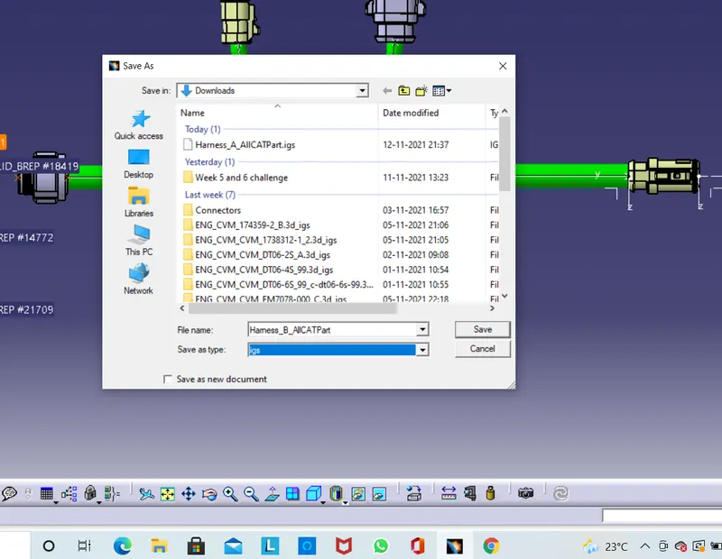
- Generate CAT.part of harness assembly and convert is in. igs format.
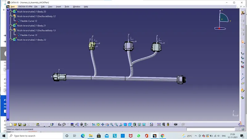
Some times it is necessary to crate aCATPart of the 3D wire harness for review or relesing purpose . This CATPart can be converted into IGES (or) STEP file.
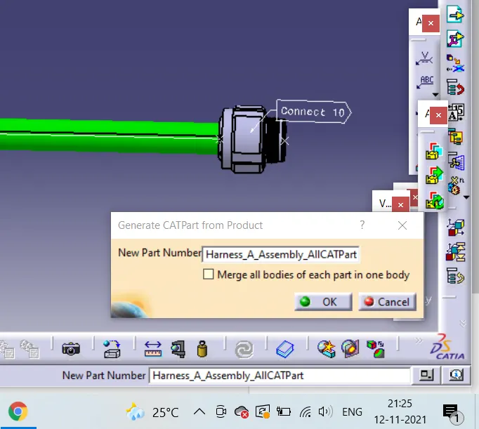
Go to mechanical assembly workbench click on Tools next we click on generate CATPart from product.
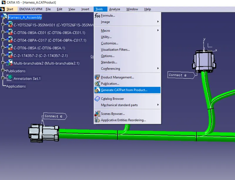
Here new window will be popup asking new part number we can select our product name" Harness_A _Assembly".In CATPart creation ALL CATPart is added.
Harness Bundle creation for given Harness Layout(Harness_B):-
In previous we can create the harness bundle creation for (Harness_A) given layout then we use the same process to our Harness_B.
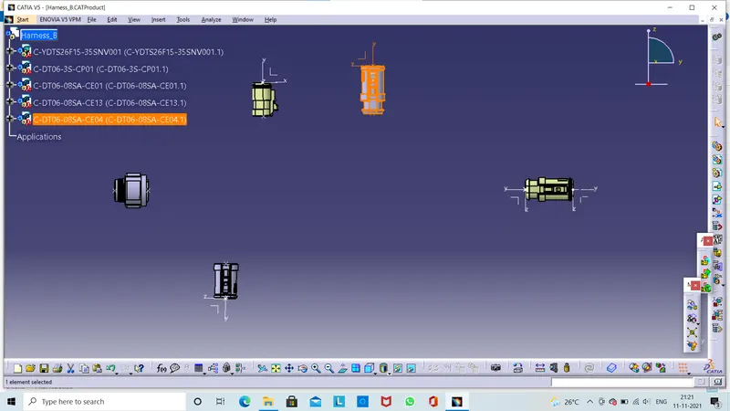
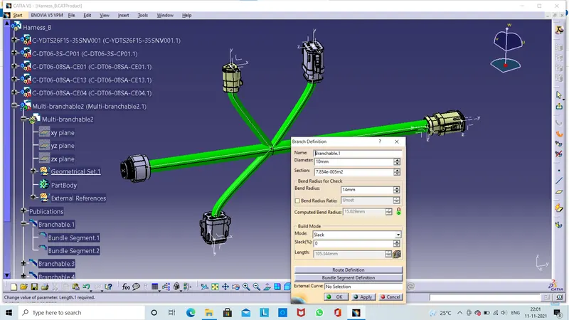
Check the bundle continuity :-
Add Annotations:-
Check the bundle warnings:-
Generate CAT.part of harness assembly and convert is in. igs format:-
".