Wiring harness design in CATIA V5 - 3D modeling Week 7 Challenge
- Wire Harness Assembly :
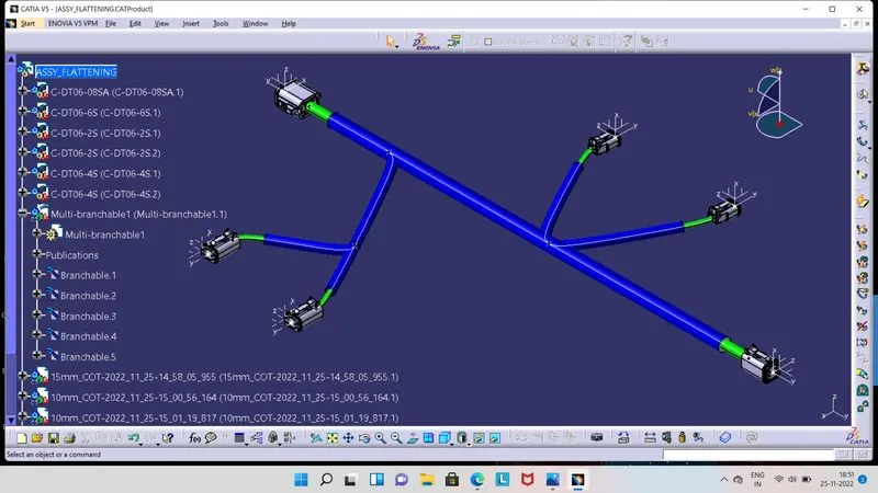
- For creating above shown Wire Harness Assembly, we have to first download the required Connectors from Internet open source and need to define them as Electrical Part.
- In Part Workbench, we have to create Points and Axis for each Connectors individually at respective places. Then switch to Electrical Part Workbench.
- Here we need use 'Define Connector', 'Define Connector Connection Point', Define Bundle Connection Point' tools for define the Connectors individually as Electrical part.
- Then create Catalog file for all Connectors and after saving all connectors add them into created Catalog file.
- Now switch to Assembly Workbench, here import all required Connectors from Catalog file and place all Connectors at their respective positions.
- Then switch to Electrical Harness Assembly, click on 'Geometrical Bundle' tool and then on name of modal tree. So icon will be changed.
- Click on 'Multi-Branchable Document', so Electrical Harness Installation Workbench will get open. Here we have to give values for Bundle Diameter, Bend Radius Ratio then click on Route Definition.
- Now click on Connetors, between which we desire bundle one by one. There is branches also at in Bundle, for that we have to use 'Add Branch Point' tool.
- Add branch point at required places on Bundle and then route the bundle from there.
- For protect the wire bundle, we can provide Corrugated Tube on Bundle. So we have to Click on 'Protective Covering' tool and select the Slit Catalog file and choose the Corrugated Tubes as per required diameter on bundle.
- Here in above image we can see that in Blue Colour, Corrugated Tube we have provide on bundle.
- As Routing of Bundle get done, then we have to switch into Electrical Harness Flattening Workbench after saving the Routing product file and create new Product file.
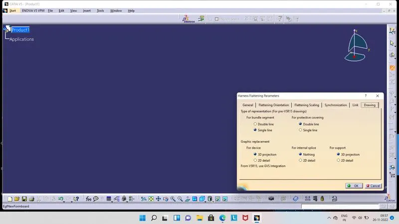
- Here we have to first define the Flattening Parameters by click on Flattening Parameter tool, one box will get appear on screen as shown in above image.
- In this box, there are many tabs we can see from above image. We have to make changes in by default sections as per our need.
- So here, we have select above shown options in Drawing tab and in remaining tabs keep by default selected options, click Ok.
- After that we can see, other tools are now active in right side toolbar, which are used in modification of flattening the routed bundle.
- Now, we have to click on Tile Vertically option from Window tab and click on 'Extract' tool and then on Bundle Routing Modal Tree.
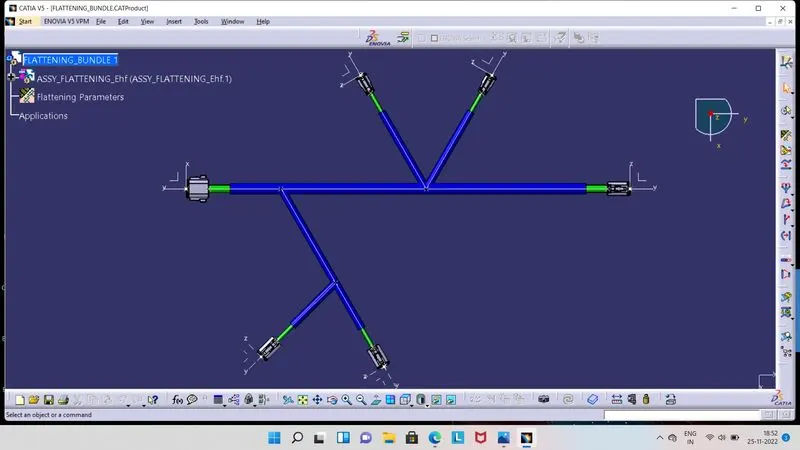
- So, that routing bundle get imported into Electrical Harness Flattening Workbench. We can see that from above image in Modal Tree, _Ehf name section is add on in modal tree.
- Now, we need to flatten this routing bundle. Click on Flatten tool and select desire plane and select routing bundles and Ok. Hence, routing bundle get flatten now.
- We can see from above image, in this way routing bundle can get flatten.
- 2D Drawing of Flatten Routing Bundle :
- For convert the flatten routing bundle into 2D drawing, we need to create new Drawing file by click on File tab and select New option and then Drawing option.
- Now, select sheet size and landscap mode then Ok. Now we are in Drawing sheet. Here click on Front View tool and go to the flatten routing bundle and click on connetcor surface.
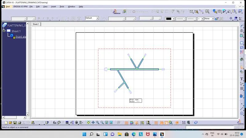
- So, 2D view of flatten routing bundle will be appear in Drawing Sheet. Here we have to right click on red dotted box.
- Then select Properties option and View tab. Now there are many option visible, we have to enable 3D Wireframe and as per requirement enable 3D Colour from Dress-up section.
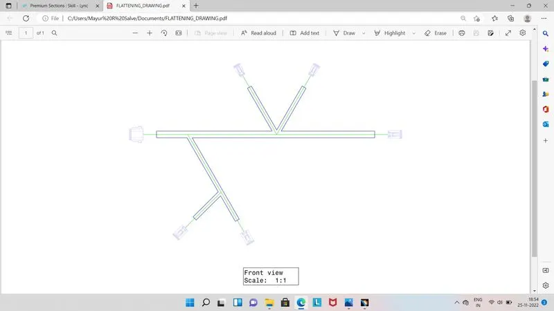
- In above image we can see that, Single line is for wire bundle and Double line for Protective Coverings. This setting we have selected in Flattening Parameters.
- In this way 2D drawing of flatten routing bundle can be done.
- Snapshot of Pdf ( Flatten Routing Bundle ) :