Wiring harness design in CATIA V5 - 3D modeling Week 7 Challenge
REPORT
Step1: first step is dowload the connector in the TE.com and the all the connectors are defined in the electrical work bench.
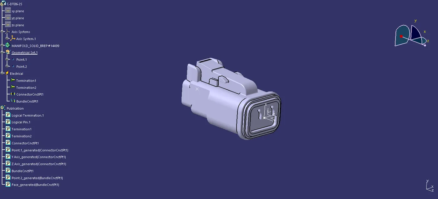
Step2: connectors are defined ,define connector tool in electrical work bench after that of define connector connection point.
Step3:And define bundle connection point in the connector.
Step4: in define conector connection point in using the point in middle of the connector face and that is orgin to create a axis for the orientation and coincidence parpouse of the axis.
Step5:And then connectors are added into the catelogue for the later use purpose and easy to find the part.
Step6: create the product file in assembly work bench and another product file also create for the gementrical bundle in that product part need to change in the electrical file so we need to use the geomentric bundle tool in electrical harness assembly work bench.
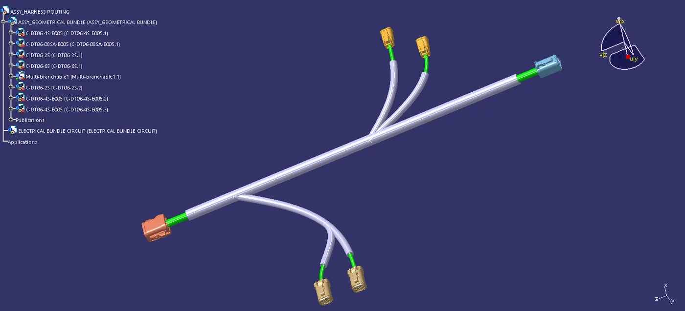
Step7: In the copy paste the all the connector and then assemble for the given dimension. after that of move to the electrical harness assembly , then using the branch definition tool for the creating the routing of the bundle.
Step8: After that of the protrecting covering tool is used for the proceting cover built in the cover is buit it and saved in catelogue already so took that for the part in the catelogue.
Flattening
Step 1: change the setting for the flattening the woring harness.
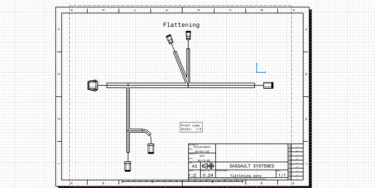
Step 2: In using the flatten tool to select all the routing and branches .
Step 3: created the flettening wiring harness. and the required in rotate the connector then sync the harness.
Drawing
step 1: create a new drawing sheet , as per the iso standard then the using front view tool make a harness in a front view .
step 2: In harness having only the one view so then move the flattening workbench change a drawing setting for a 3D projection then only the connector are show like 3D.and using the edit tool for backround sheet and tool option is a frame a title and make boundary of the sheet.