Wiring harness design in CATIA V5 - 3D modeling Week 7 Challenge
Objective
- Flattening the given harness assembly
- Placing the flattened view on drawing sheet
Procedure
Flattening the given harness assembly
- Switching to the electrical harness flattening workbench
- Create new product file
- Switch to the electrical harness flatten workbench
- Set the harness flattening parameters as shown in images below
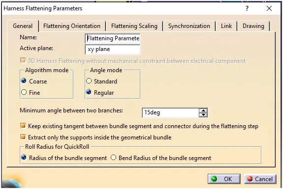
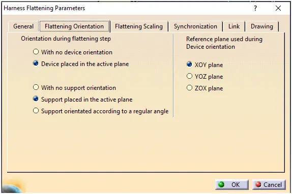
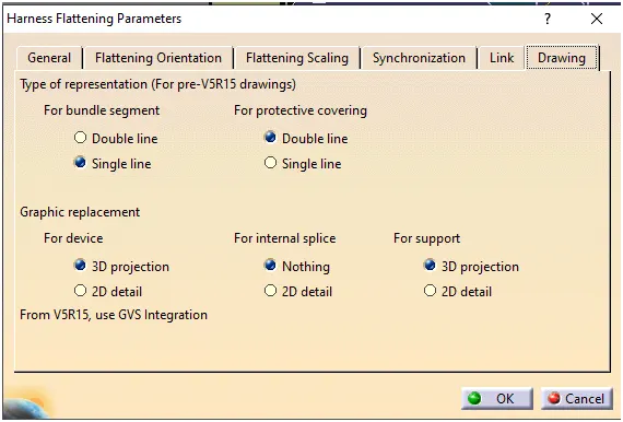
- Import the harness assembly by using ‘Extract’ command
- After importing the harness assembly, Use ‘Flatten’ command to flatten the harness assembly which is shown in the image below. In CATIA flattened model will be saved as ‘_Ehf’.
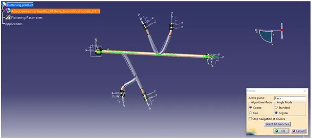
- Completely flattened harness layout is shown in the image below. CATIA provides multiple commands to modify the flattened assembly. They are ‘Straighten’, ‘Rotate’, ‘Bend’, ‘Roll’ etc. We can use these commands if necessary
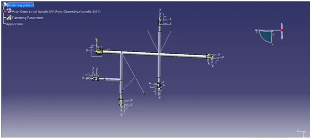
2. Placing the flattened view on drawing sheet
- Create new drawing in CATIA workbench
- Select the ‘Front view’ command in CATIA Drawing workbench
- Now switch to ‘Electrical harness flattening’ workbench. Select the face of the connector
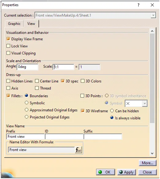
- Place it on the drawing sheet in proper orientation. After this we need to set some properties in drawing, which is shown in image below
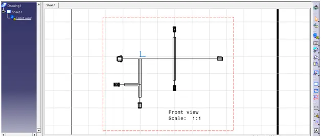
In the drawing sheet ‘Branches’ are shown in single line. ‘Coverings’ are shown in double lines. ‘Connectors’ are represented in their 3D visual.
Conclusion
Given harness assembly is flattened and placed on the drawing sheet