Week 8 - Challenge 1 - Draft Analysis on a Fan Cover
Objective: To perform the draft analysis of given class A surface
Introduction
Draft is required on all parts in the direction of mold movement inorder to allow parts to release or eject from the mold properly. Adding draft helps the part to release. Most parts or applications require a minimum of half to one degree, however 3 degrees is widely accepted as the norm.
Steps:
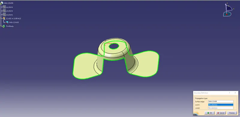
1. Check the connectivity of given class A surface to ensure there is no gap between the surfaces. This can be done by using Join or Boundary command in CATIA. By extracting the boundary of given class A surface we can visually check the connectivity of the model.
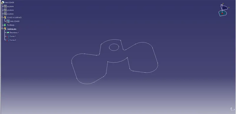
2. Deciding the component ejection direction and then setting the dummy tooling axis. Tooling axis is the line along which core and cavity will open.
3. Creation of actual tooling axis
3.1 Tooling clearing in x-direction: Insert the axis system, take the intersection of plane and the surface
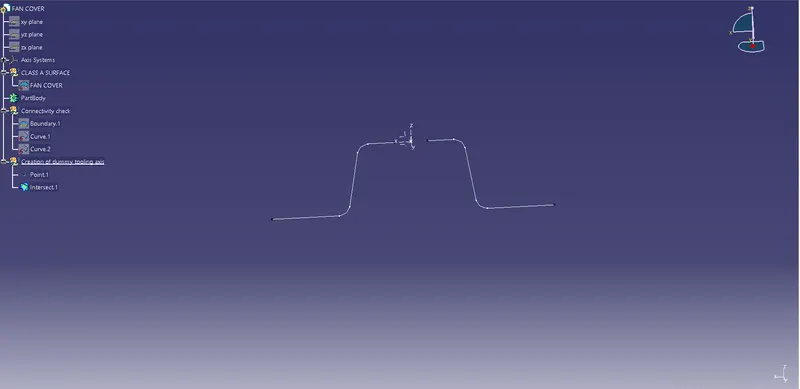
Now find the lines lying approximately parallel to dummy tooling axis. These are the lines along which draft angle will be provided.
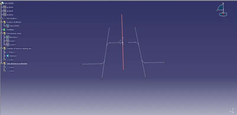
Use bisecting method to find the tool clearing in x-direction. Following is the procedure for bisection method:
- Select two points on the lines which are approximately parallel to tooling axis and create the line. Repeat the same procedure on other side of dummy tooling axis
- Create a line by selecting bisecting option in line creation dialogue box.
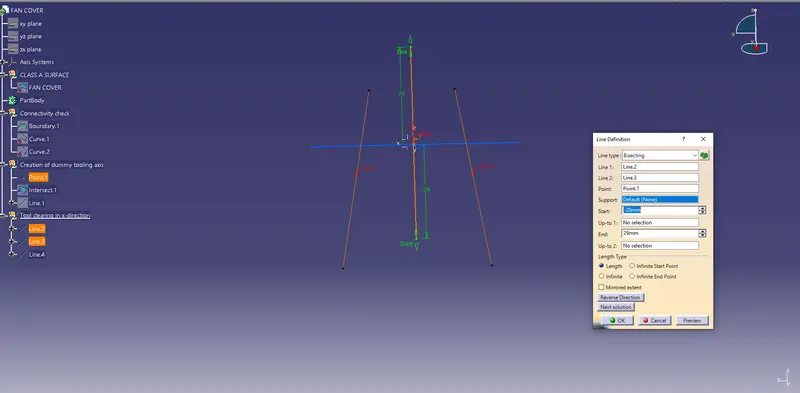
3.2 Tooling clearing in y direction: Insert the axis system, take the intersection of plane and surface.
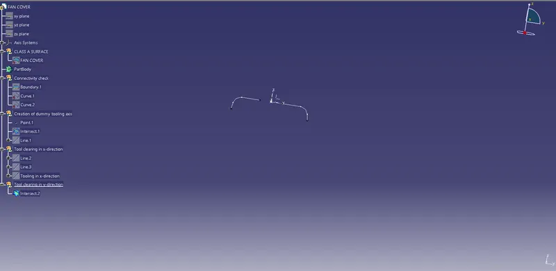
Use bisecting method explained earlier to get the tool clearing in y-direction
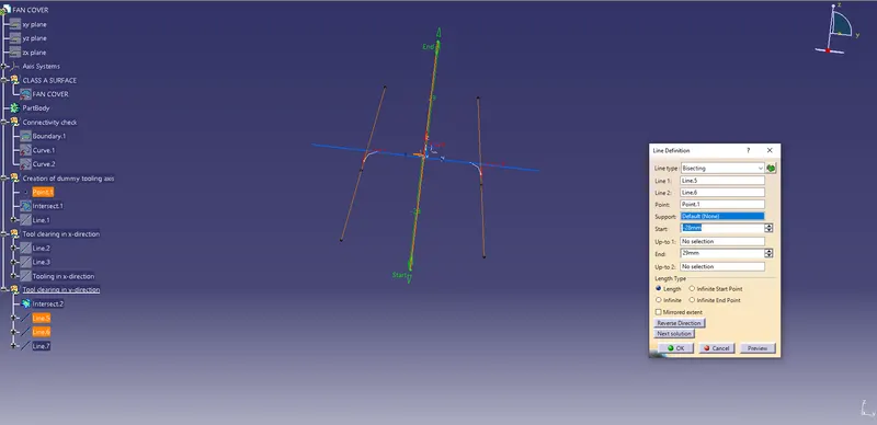
Line created by bisecting tooling clearing in x and y directions will be the actual tooling axis of the component.
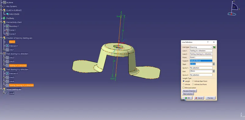
4. Draft analysis
Click on compass icon and align it with the tooling axis. Before that customize view parameter mode to material. Now click on the surface, we will get our results
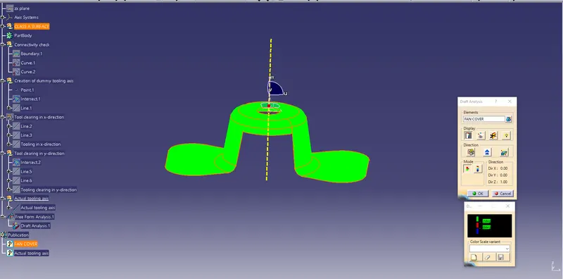
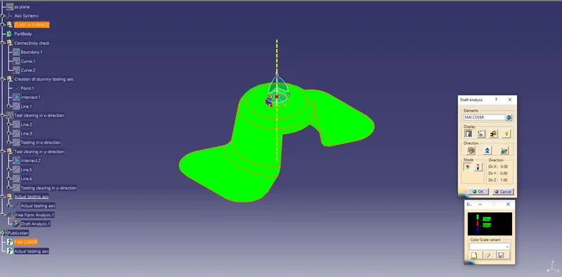
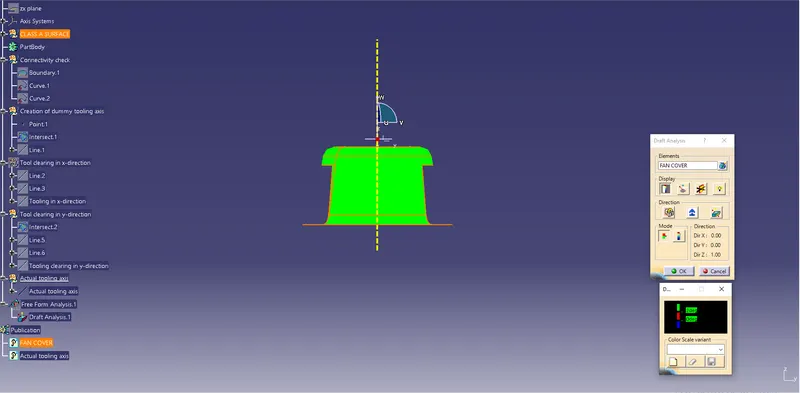
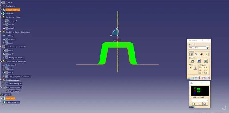
From the above image it is seen that surface in green colour has greater than 3 degree draft which is most required for tooling feasibility.
Below image shows full draft analysis
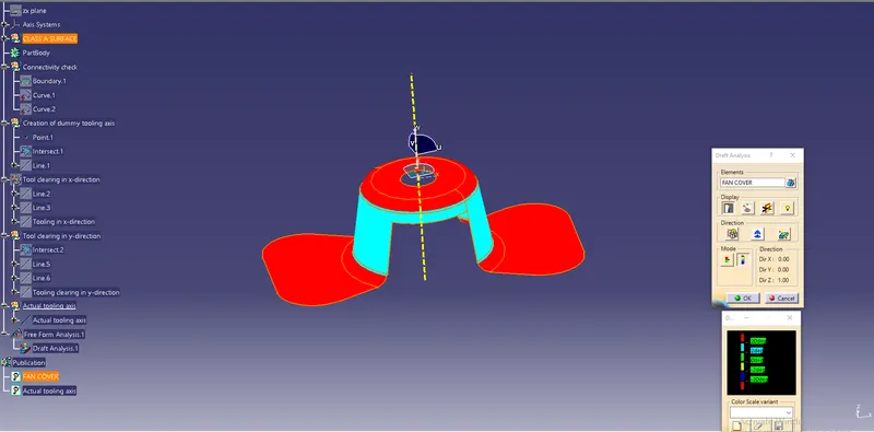
Also check the draft angle of running point on surface
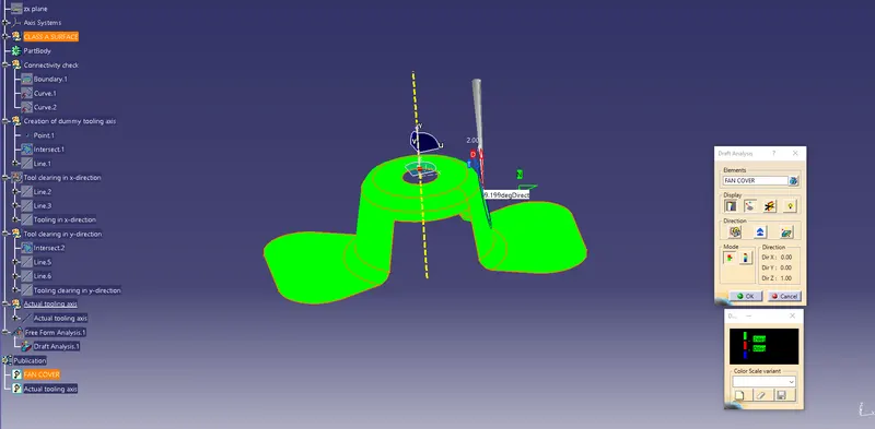
Image of the model in various orientations
Isometric view
Front view
Side view
Top view
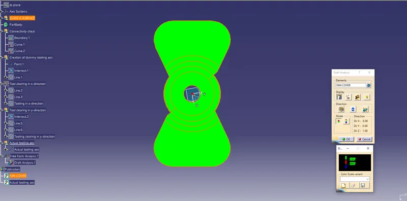
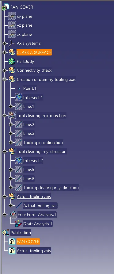
Image of the geometrical set