Wiring harness design in CATIA V5 - 3D modeling Week 7 Challenge
Report on week 7 challenge
Objective:
The objective of this report is to
- Define all the connectors and rout wires to connect the connectors.
- Then flatten the assembly.
- Finally make a drawing of the assembly using CATIA.
Define the connectors:
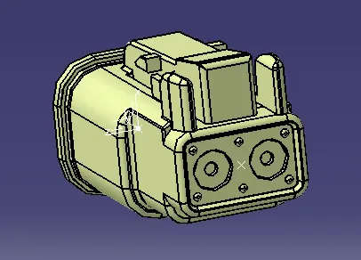
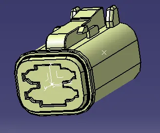
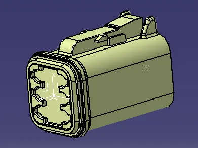
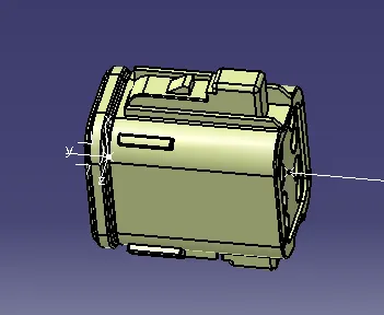
First of all, the connectors have to be defined electrically. For that, I have used mechanical part design workbench to give the necessary axis and points. Next, I used electrical part design workbench to define the connectors and also their bundle entry points and connector connection points.
Image of the connectors:
Creating harness assembly:
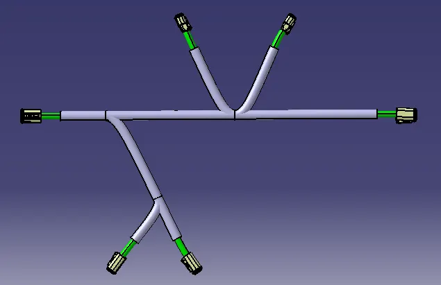
Now, all the connectors are opened in one product assembly. They are adjusted in the proper location by using snap, compass and manipulation tools. Then, I have moved to the electrical harness assembly workbench to rout the wires. Here, I have used the geometrical bundle command first. Then I have used the multibranchable command to create a multibranchable file in the assembly. Then I have used the bundle definition command to add the bundle to rout them.
Adding protective covering:
For adding protective covering I have exited from branchable command. Then, in the harness assembly workbench, I have used the protective covering command to give the routed wires a protective coat.
Image of the modelled product:
Harness flattening:
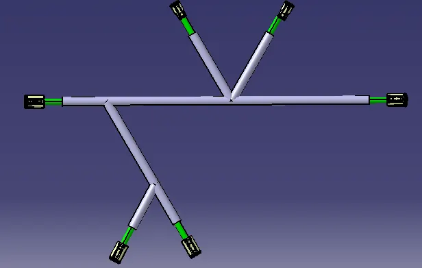
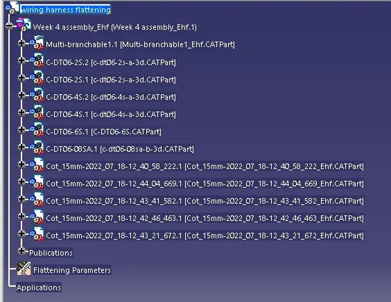
Create a new product file for harness flattening. First, I have to define the harness parameter. I have changed the active plane to a flat plane of one connector. I have kept the flattening orientation, scaling, tolerance, synchronization and link as the default. I have used ‘single line’ representation for bundle segments and ‘double line’ for protective covering. I have used ’3D projection’ representation for devices and also for support.
Then, I have used the extract command to extract the harness assembly in the flattening workbench. After that, I have moved to the assembly workbench to arrange the connectors in proper direction. I have used flatten command to flatten the assembly.
Image of the flattened product:
Creating Drawing:
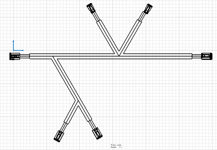
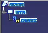
Create a new drawing part where I have selected the ISO-A0 sheet standard. Now, I use the front view command and select the flattening product. Then select the same surface of the harness assembly which was earlier taken for the flattening of the model. Now, keep the visibility of the wireframe on. Thus the assembly is properly drawn in the drawing part file.
Image of the drawing:
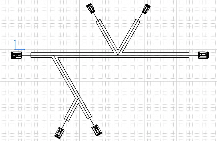
Image of drawing when the representation of bundle system is changed to double line in flattening parameter:
Conclusion:
Harness assembly, flattening and drawing are done using different workbenches in the CATIA environment.