Wiring harness design in CATIA V5 - 3D modeling Week 2 Challenge
- Report on wiring harness challenge 3
Objective:
To define the electrical equipment in the Catia V5 environment and create a harness assembly of that connectors and mounting clips.
Introduction:
To make the final assembly we need different workbenches like Part Design, Electrical Part Design, Assembly Design, and Electrical Assembly Design. The process is followed by various steps I will cover in this report.
Set-Up:
First, open the Catia V5 Software and create a catalogue by clicking new then clicking catalogue document then select the name of the catalogue and properties of the catalogue. Now open the connectors and mounting clip into the Catia software and save all the components as cat parts.
Defining the Female Connector Part of the product:
Creating points: In the female connector part both the male and mounting clip will be fitted. So, we need two axis systems, one is for the connector and one is for the mounting clip. First, create points where connection point is to be made. For the female part, three points are to be created. One point should be for the bundle connection, one is for the connector connection and one is for the cavity connection. For creating points look for a similar geometry to make a between relation. Also, you can select curve option, edge option and face option to create a point.
Creating Axis: After creating the points, the axis needs to be defined for the connector and for the mounting clip. For the connector, the axis should be oriented using a specified formula. Like, the Y-axis should be directed perpendicular to the mating surface and it will be facing towards the mating connector. And X-axis should be directed to the locking system And Z-axis should be pointing across the connector from left to right.
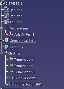
Define the part as an electrical connector: Now change the part workbench and select the electrical part design workbench. In the electrical assembly workbench, first, define the part as a connector by using the define connector command. In this command, we have to select the part body first and have to give the number of connection points present in the connector. Here we have three connection points for the female part.
Define the bundle connection point:
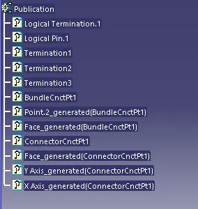
After defining it as an electrical component, we have to define the other connection points. First select the bundle connection point command then select the connector, after that in the representation we have to select the face in which connection should be made, and then we have to select the point which we had made earlier for the bundle connection. Then, for the initial condition, we have to select the mating face again.
Define the connector connection point:
Now, select the connector connection point command, then select the part body. Then select the point which was made earlier for the representation. Then select the mating face for the contact option. Select the Y-axis for the coincidence and the X-axis for the orientation of the connector connection.
Define the cavity connection point:
Now, select the cavity connection point command and then select the part body. Then for the representation select the point which was earlier created. Then, select the mating face as contact and for the coincidence select the Y-axis and for the orientation select the X-axis.
And finally, use the store device option to save the connector in the catalogue.
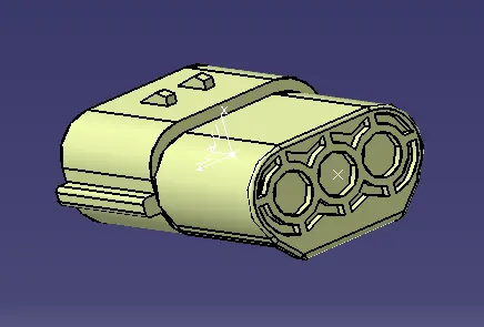
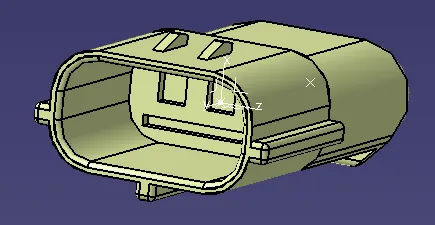
Image of the modelled part:
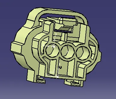
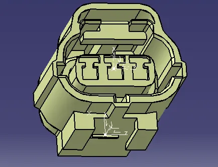
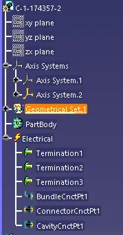
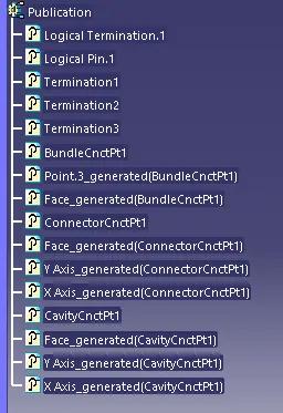
Defining the Male Connector Part of the product:
Creating points:
The male connector has three connection points and it will be attached to the female connector. So, a point is created at the connector side and another point is created at the bundle entry side of the connector.
Creating axis:
After creating the points, one axis is created at the connector connection side of the male connector. The Y-axis should be in the mating direction and X-axis should be in the locking direction.
Define the part as an electrical connector:
Now go to the electrical part design workbench and then select the body and give three connection points to make it an electrical part.
Define the connector connection point:
Use the connector connection point command and select the part and then select the point which was made earlier for the representation. Then select the mating face for the contact option. Select the Y-axis for the coincidence and then select the X-axis for the orientation. And finally, use the store device option to save the connector in the catalogue.
Image of the modelled part:
Defining the mounting clip:
Creating point:
In the part design workbench, create a point at the mating portion of the mounting clip.
Creating axis:
An axis is created at the point which is created on the mounting clip. The Y-axis should be in the mating direction and the X-axis should be in the locking direction.
Define the part as a mounting device:
Now, open the electrical part design workbench and select the define mounting equipment command and select the part and define it as a mounting device.
Define the cavity:
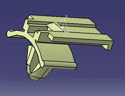
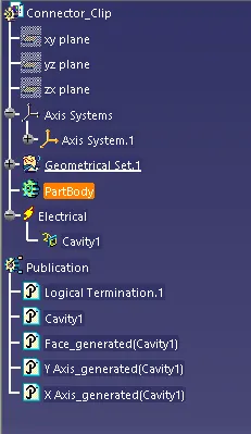
Now use the define cavity command and select the clip and then select the point which is made earlier for the cavity connection for the representation. Then, select the mating face for the contact option, select the Y-axis for coincidence and select the X-axis for the orientation. And then store it in the catalogue.
Image of the modelled part:
Assembly making:
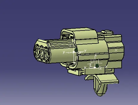
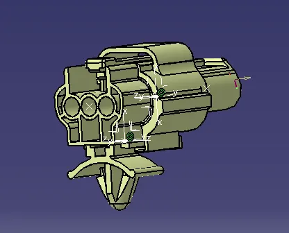
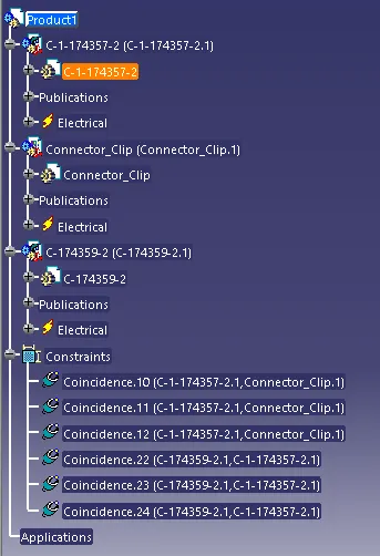
Now, change the workbench to the assembly design workbench. Copy the female connector and the male connector and paste them into the assembly workbench. Then use the manipulation command to keep the parts at a proper location before moving to the final assembly. Then move to the electrical assembly workbench and use the connect electrical device command to connect the male connector with the female connector. It will connect automatically at the connector connection point. Again, import the mounting clip into the assembly workbench then use the manipulation command to keep the clip in a proper position. Then change the workbench into the electrical assembly design workbench. After that use the connect electrical device command to connect the mounting clip with the female part. It will be automatically connected at the cavity connection point. Finally, save this assembly.
Image of the modelled part:
Conclusion:
So this is the understanding of defining the connectors and clip using CATIA V5 software. I have defined connectors and clip separately and assemble them using different workbenches in the Catia V5 environment.