Radar Mast & Final Assembly of Yacht
RADAR MAST :
YACHT ASSEMBLY:
REPORT ON YACHT DESIGN:
Aim and Objective:
- To design all the parts of a Yacht under the part modelling environment in SolidWorks separately.
- Assembling all the parts to complete the final yacht design.
And finally, create a realistic photo rendering using SolidWorks Visualize and Photoview 360.
What is Part modelling?
To design realistic models, we need to know about the configurations and positions of all the model parts. Part modelling is designing all the parts of a model separately by keeping some design references useful during assembly. Here all the parts are made in the Solidworks environment.
Parts to be modelled to design Yacht:
- Blueprint setup
- Propeller
- Radar
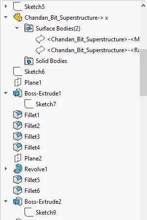
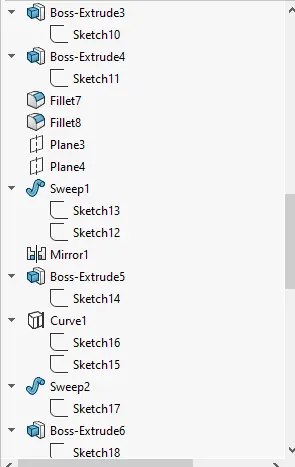
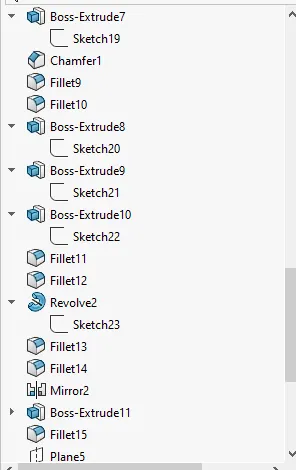
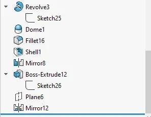
- Radar-Mast
- Garage door
- Hull
- Front Seat
- Middle Seat
- Rear Seat
- Superstructure
Blueprint setup:
A blueprint is a design or a technical drawing that explains the overall details of the component. It is very useful to design the parts of a realistic model. It shows the specific parts inside a model precisely.
Propeller:
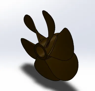
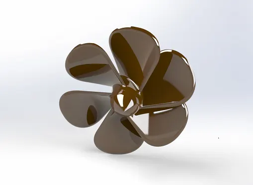
A propeller is a rotating fan-like structure that is used to propel the ship by using the power generated and transmitted by the main engine of the ship. The transmitted power is converted from rotational motion to generate a thrust which imparts momentum to the water, resulting in a force that acts on the ship and pushes it forward. Propeller works based on Bernoulli’s principle and Newton’s third law. In this ship design, three propellers are fitted.
Features/Commands used to design Propeller:
- 2-D Sketch-- A 2-D Sketch consists of a two-dimensional element. It is helpful to make an extrude.
- Revolve-- Revolves add or remove material by revolving one or more profiles around a centerline.
- Cut Extrude—Extrude-cut helps to remove materials from the 3D model. It is just the opposite of extrude boss/base feature because it cuts a sketch profile while extruding. You can cut in both directions and are mainly used for creating holes, channels, slots etc
- Lofted boss/base--Loft creates a feature by making transitions between profiles. A loft can be a base, boss, cut, or surface. You create a loft using two or more profiles.
- Fillet----Fillet/Round creates a rounded internal or external face on the part.
- Circular pattern-- Circular pattern is used to create multiple instances of one or more features that you can space uniformly around an axis.
Design Methodology:
Create 2-D sketches in the selected planes—then use revolve boss/base option to get a 3-D part of the propeller base—then use the loft command to make one blade—then use the cut extrude command to get the appropriate shape of the blade—then use fillet to give fillet at the required location—use a circular pattern to make the other blade—finally give the appearances.
Images of the modelled parts:
Radar:
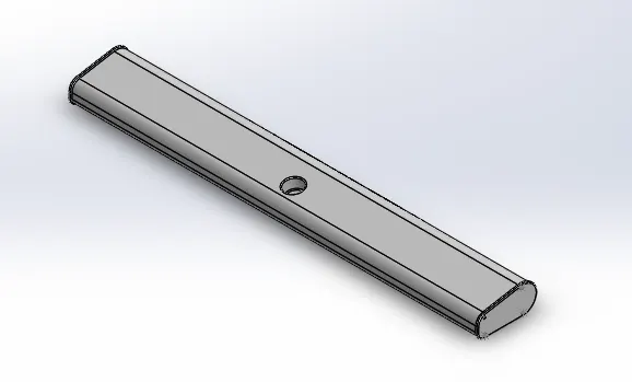
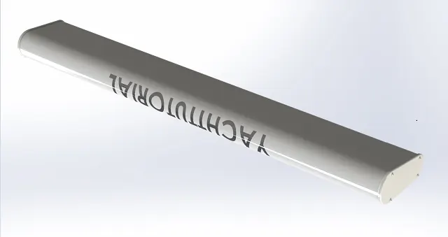
Radar is an instrument that can detect surrounding objects using radio waves. So, it helps to detect the location of ships, buoys or birds while sailing on the sea. They are electronic navigation instruments that use a rotating antenna to sweep a narrow beam of microwaves around the water surface surrounding the ship to the horizon, detecting targets by microwaves reflected from them, generating a picture of the ship’s surroundings on a display screen.
Features/Commands used to design Radar:
- 2-D Sketch
- Boss Extrude-- The Boss-Extrude/Base feature will project a 3D model with the selected sketch or face.
- Cut Extrude
- Mirror-- It is used to create a copy of a feature, (or multiple features), mirrored about a face or a plane.
- Split line-- The Split Line tool projects an entity (sketch, solid, surface, face, plane, or surface spline) to surfaces or curved or planar faces. It divides a selected face into multiple separate faces.
- Fillet
- Sketch pattern
Design Methodology:
Create 2-D sketches in the selected planes—use the extrude boss command to create a 3-D part model—then use the fillet and cut extrude base command to create the desired model—use sketch pattern to create screws in the radar part—then use split line option to write text on the modelled part.
Image of the modelled part:
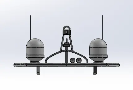
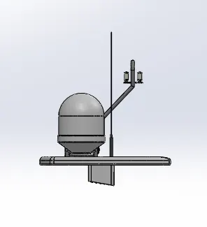
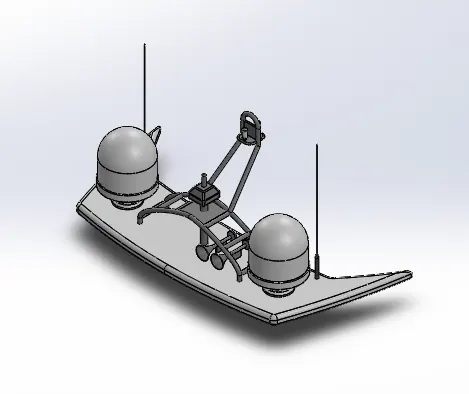
Radar-Mast:
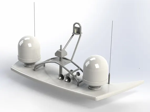
Radar-Mast is present at the top of the superstructure. The mast carries radio and radar aerials, signalling equipment (including halyards to hoist flags), navigation lights and an anemometer.
Features/Commands used to design Radar-Mast:
- 2-D Sketch
- Revolve
- Boss Extrude
- Sweep boss/base-- a sweep is a tool that creates a solid, a cut or a surface feature by moving a profile along a path. To create a solid, use the Swept Boss tool to move a profile along a path. The profile can contain one or more closed contours.
- Chamfer-- The chamfer tool creates a bevelled feature on selected edges, faces, or a vertex.
- Fillet
- Mirror
- Curve
- Shell-- The Shell feature hollows out the inside of the solid, leaving a shell of a specified wall thickness.
- Dome-- It creates a dome that is tangent to the adjacent cylindrical or conical face.
Design Methodology:
Create 2-D sketches in the selected planes—then use the boss extrude, fillet and chamfer command to create the base of the radar mast—then use revolve, fillet and dome command to make the radar parts—use the mirror command to make the full structure of the radar mast—then use revolve, dome, fillet and mirror commands to make the two horns-finally give the appearances.
Image of the modelled part:
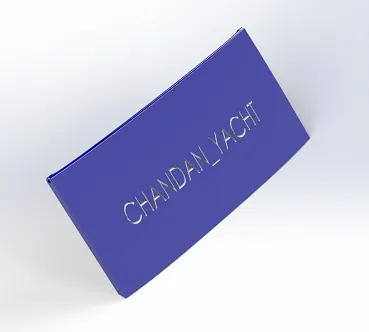
Garage Door:
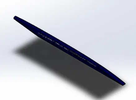
A garage door is a large door on a garage that opens either manually or by an electric motor. Garage doors are frequently large enough to accommodate automobiles and other vehicles. The garage door is placed here inside the hull to keep automobiles like cars or bikes inside it.
Features/Commands used to design Garage Door:
- 2-D Sketch
- Cut Extrude
- Fillet
- Mirror
Design Methodology:
Part of the garage door is imported from the hull body—then the parent-child relationship must be broken before going further—then use fillet command to give the part a good fillet—then mirror it concerning the side face of the Garage door part—write on the garage door by using text and cut extrude command—then give the part appropriate appearances.
Image of the modelled part:
Seats:
Seats are the structure where the people can seat. In this Yacht model, there are three seats present —
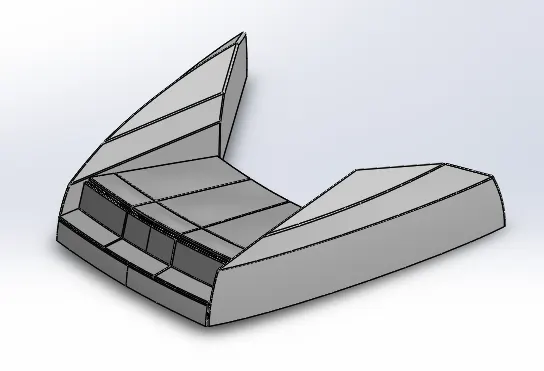
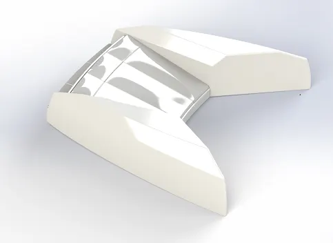
Front Seat:
It is present on the front side of the Yacht model on the hull.
Features/Commands used to design Front Seat:
- 2-D Sketch
- Surface sweep-- Sweep surfaces are surfaces that are generated from a section curve positioned along a path.
- Surface Extrude-- You can create extruded surfaces from models that include 2D or 3D faces and knit the extruded surfaces to surrounding features.
- Surface trim-- Create two or more surfaces that intersect at one or more points or create a surface that intersects with a plane or has a sketch on its face.
- Surface fill-- The Surface fill feature constructs a surface patch with any number of sides, within a boundary defined by existing model edges, sketches, or curves, including composite curves.
- Surface knit-- The Knit Surface tool is used to combine two or more faces and surfaces into one.
- Chamfer
- Revolve
- Cut extrude
- Dome
- Fillet
- Mirror
Design Methodology:
Part of the Front seat is imported from the hull body—make 2-D sketches in the selected plane--use surface sweep, surface loft, surface extrude and surface trim features to create one side of the front side—then use the surface fill option to get a solid body—use revolves, chamfer, fillet and dome feature to create the seat portion of the front seat—then use the mirror feature and give fillet to the appropriate position to get a solid body of the front seat.
Image of the modelled part:
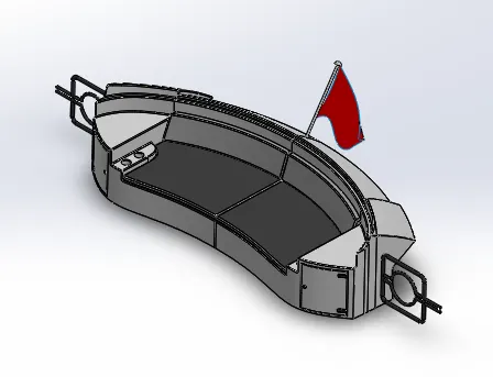
Rear Seat:
It presents at the rear part of the ship.
Features/Commands used to design Rear Seat:
- 2-D Sketch
- 3-D Sketch
- Surface sweep
- Surface offset--The Offset Surface tool creates a new surface body from an existing set of faces. The faces may be solid or surface faces.
- Surface trim
- Ruled surface--The Ruled Surface command creates surfaces that extend out in a specified direction from selected edges.
- Surface Extend— This command is used to extend one or more surfaces as required.
- Surface knit
- Surface Extrude
- Surface loft
- Cut extrude
- Boss Extrude
- Chamfer
- Fillet
- Mirror
- Sweep boss
- Revolve
Design Methodology:
Part of the rear seat is imported from the hull body—then make 2-D sketches in the selected planes—then use surface offset, surface sweep, and surface trim to make one side of the rear seat—use surface extrude, surface offset, revolve, fillet and chamfer to make the sitting place on the rear seat—use mirror feature to get the full 3-D body of the rear seat.—now make some -3-D drawings – then use the surface loft to make a flag on the tail part of the Yacht. Finally, give the appearance to the model.
Image of the modelled part:

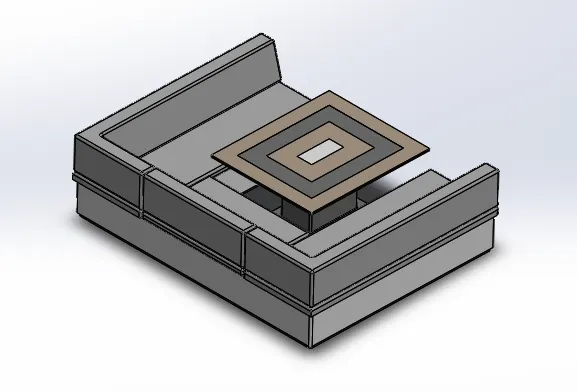
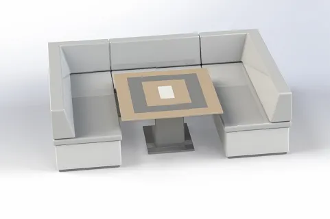
Middle Seat:
It presents in between the front and rear seat towards the end of the hull of the ship.
Features/Commands used to design Middle Seat:
- 2-D Sketch
- Boss Extrude
- Cut Extrude
- Fillet
- Chamfer
- Mirror
Design Methodology:
Part of the middle seat is imported from the hull body—draw 2-D sketches in the selected planes—use extrude boss command to create a base of the middle seat—now give the parts a proper fillet and chamfer—mirror the part to make the middle seat—now draw a 2-D sketch in front of the rear seat—use extrude boss command to make it a 3-D object—give chamfer and fillet in the desired location—finally give it a good appearance.
Image of the modelled part:
Hull:
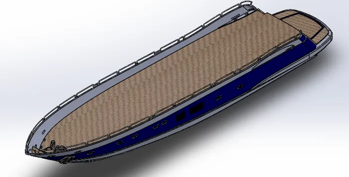
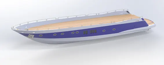
Hull is the water weight of a ship. Hull may be fully or partially covered with deck. Hull is the main body of a ship. It contains cargo in different compartments. And it also contains the engine room of a ship which houses the propulsion machinery, stores, steering compartment etc. This is the part that gives buoyancy to the ship that keeps it afloat.
Features/Commands used to design Hull:
- 2-D Sketch
- Boss Extrude
- Cut Extrude
- Fillet
- Chamfer
- Composite curve
- Surface loft
- Surface trim
- Surface Extrude
- Surface Knit
- Surface fill
- Shell
- Sweep
- Dome
- Revolve
- Linear patter
- 3-D Sketch
- Mirror
- Split
- Surface offset
Design Methodology:
Draw sketches as per the blueprint—then use the composite curve to draw a curve in a 3-D location—use surface loft command to create the outer surface of the yacht—use surface fill, surface trim, boss extrude, cut extrude, shell feature to create more parts in the Hull one by one—use composite curve and sweep boss base command for the railings—use revolve, boss extrude, cut extrude, fillet and chamfer for making the attachment of the propeller—make an anchor in the surface of the hull by using 2-D sketches, boss extrude, cut extrude, and fillet commands—use split line command to create an extra feature in the face of the hull—now knit everything and use mirror option by taking the midplane as a reference—now give this part appropriate appearances and also add decals of desk surface and stair steps.
Image of the modelled part:
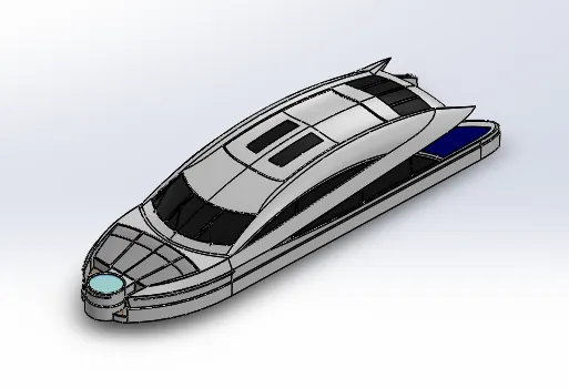
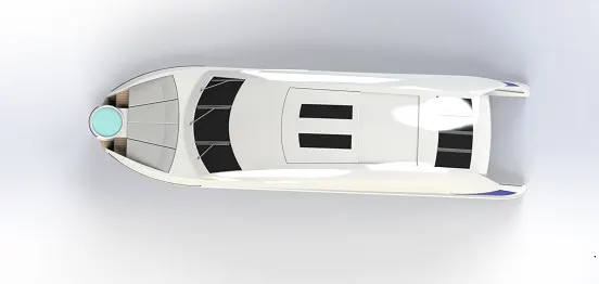
Superstructure:
The Superstructure is a part that is present above the deck surface of a ship. The word “Superstructure” comprises two Latin words “Super” and “Structure”. “Super” means “in addition” or “in excess of”, whereas the stem word “Structure” means “to build” or “to heap up”. Thus, superstructure means adding construction to an already existing structure. On the upper part of this, the radar mast and radar are fitted.
Features/Commands used to design Superstructure:
- 2-D Sketch
- Surface Extrude
- Surface Sweep
- Surface Knit
- Ruled Surface
- Fillet
- Surface Trim
- Composite curve
- Surface fill
- Surface loft
- 3-D sketch
- Surface Extend
- Boss Extrude
- Cut Extrude
- Delete Face
- Offset Surface
- Thicken
- Dome
- Sweep base
- Split line
- Mirror
- Chamfer
Design Methodology:
The surface of the deck is imported from the hull body as a reference for the Superstructure--use surface extrudes, surface sweep, surface knit and fillet to make the side of the superstructure—use surface loft, surface fill and surface trim option to make the side of the Superstructure—use surface loft, surface sweep, surface trim, surface fill and surface knit option to make the other parts of the superstructure one by one –for the surface knit the knitted edge must be turned into black or else it will be a problem while mirroring and making a solid body of that—after the knitting use mirror option to create the full model of the superstructure—now use boss extrude, cut extrude fillet option to create the rear door and windows of the superstructure—now give the superstructure appropriate appearances and decals.
Image of the modelled part:
What is an Assembly?
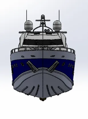
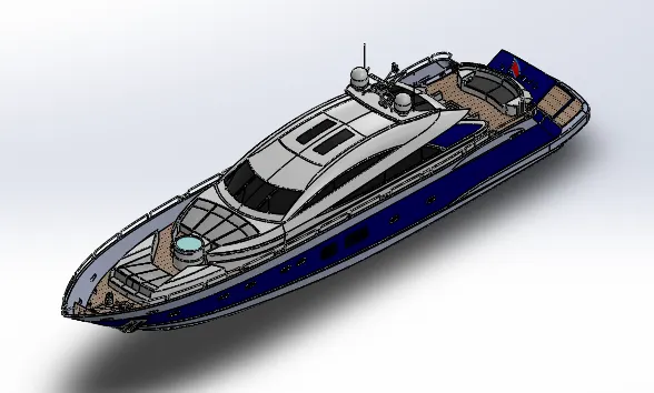
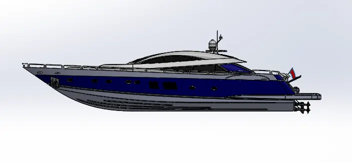
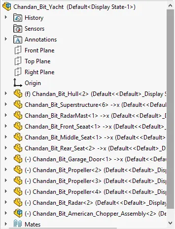
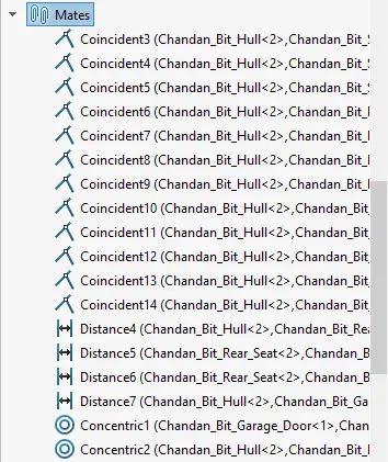
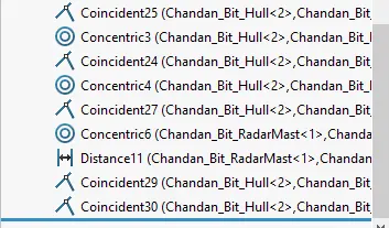
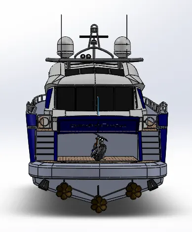
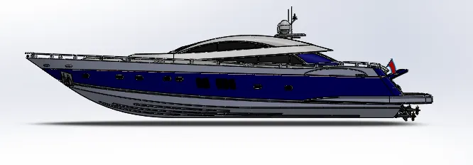
An assembly is a document where all the parts, features and sub-assemblies are mated together. Here all the parts of the yacht are inserted one by one and mate with the hull using manual mates. After the assembly, the ship is fully ready for rendering.
Methodology:
Import the hull part first and fix it—then import the other parts one by one—then give the parts appropriate mate such as coincident, concentric, distance mate with the hull—finally, add decals to give it a good look.
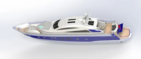
Image of the assembly of Yacht:
Photorealistic rendering:
It is a digital process using a 3-D CAD model within a software package to create a digital image of the model. The result is a rendering image that is hard to distinguish from a photograph of a real-life object.
Methodology:
Use SolidWorks visualize to give a good rendering to all the individual parts and the assembly of the Yacht model.
Image of the rendered Yacht:
Default environment:
Sea Landscape:
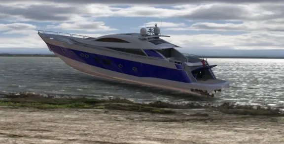
Conclusion:
All the parts of the Yacht are designed using SolidWorks. After that, all the parts are assembled together using SolidWorks. Finally, scene set-up and camera set-up are done after giving the model a good appearance. The rendering is done using photo view 360 and SolidWorks Visualize software.
I am not able to upload the zip file so I am uploading it into google drive and sharing the link:
link: https://drive.google.com/file/d/1Gg-DqQxo9lTafE9aJTVHvFRTOSKozsxc/view?usp=sharing