Photo Realistic Rendering
REPORT ON ASSEMBLY OF AMERICAN CHOPPER MODEL
Aim and Objective:
- To design all the parts of an American Chopper under the part modelling environment in SolidWorks separately.
- Assembling all the parts to complete the final chopper design.
- And finally, create a realistic photo rendering using SolidWorks Visualize
What is Part modelling?
To design realistic models, we need to know about the configurations and positions of all the model parts. Part modelling is designing all the parts of a model separately by keeping some design references useful during assembly.
Parts to be modelled to design American Chopper:
- Transmission Belt
- Kick Stand
- Front Fender
- Rear Fender
- Oil Tank
- Chain
- Pedals
- Front Wheel
- Rear Wheel
- Front Fork
- Chassis
- Engine
- Gas Tank
Transmission Belt:
Transmission belts transmit power from one shaft to another using pulleys that rotate at the same or different speeds. The amount of power transmitted depends upon the following factors:
- The velocity of the belt.
- Tension on the belt
- Surrounding conditions
The transmission belt is used in automobiles, lathe machines, milling machines, conveyors, etc.
Features/Commands used to create Transmission Belt:
- 2-D Sketch – A 2-D Sketch consists of a two-dimensional element. It is helpful to make an extrude.
- Offset-- The Offset feature creates a proportionally larger or smaller layer of your design.
- Boss Extrude--The Boss-Extrude/Base feature will project a 3D model with the selected sketch or face.
- Fillet--Fillet/Round creates a rounded internal or external face on the part.
Design Methodology:
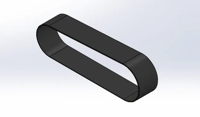
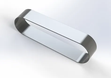
Create a 2-D sketch of the outer side of the transmission belt –then use extrude boss/base command to get a 3-D part then fillet the side of the transmission belt as required.
Image of the modelled part:
Kick Stand:
A Kick Stand is a part that allows the vehicle to be kept upright without leaning against another object. A kickstand is a piece of metal that flips down from the vehicle frame and contact with the ground. It is generally located at the middle portion of the bike or towards the rear. Kickstands can be made of steel or cast aluminium.
Features/Commands used to create Kick Stand:
- 2-D Sketch
- Boss Extrude
- Cut Extrude—Extrude-cut helps to remove materials from the 3D model. It is just the opposite of extrude boss/base feature because it cuts a sketch profile while extruding. You can cut in both directions and are mainly used for creating holes, channels, slots etc.
- Dome--It creates a dome that is tangent to the adjacent cylindrical or conical face.
- Split—The Split feature is used to create multiple parts from an existing part. You can create separate part files and form an assembly from the new parts. You can split one or more solid or surface bodies.
Design Methodology:
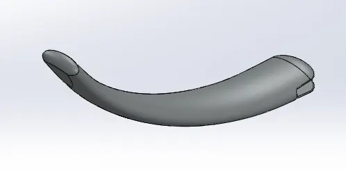
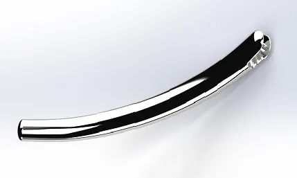
Create three 2-D sketches in different planes–then use the lofted boss/base command to get a 3-D part then—use the dome feature to the sides of the kickstand as required—use the split feature to split some portion of the part—then give fillet to the part as required.
Image of the modelled part:
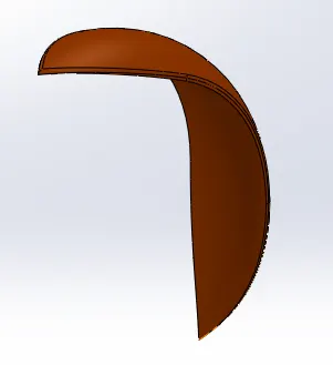
Fenders:
These are the parts that are used to prevent sand, mud, rocks, liquids, and other road sprays from being thrown into the air by the rotating tire. There are two fenders on a bike. The front fender is located near the front wheel and the Rear fender is located near the rear wheel.
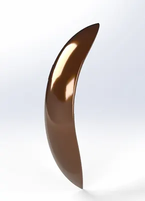
Front Fender:
The front fender is located near the front wheel and gives protection to the parts of the front wheel from the dust particles.
Features/Commands used to create Front Fender:
- 2-D Sketch
- Revolve-- Revolves add or remove material by revolving one or more profiles around a centerline.
- Split-- Use the Split feature to create multiple parts from an existing part. One can split one or more solid or surface bodies.
- Fillet
Design Methodology:
Create a 2-D sketch in the selected plane keeping one centerline for the revolve command—then use revolve boss/base command to create a 3-D model—then use the split command to cut the fender accordingly—then use the fillet command to give the fillet at the required location.
Image of the modelled part:
Rear Fender:
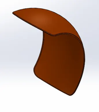
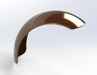
The rear fender is located near the rear wheel and gives protection to the parts of the rear wheel from the dust particles.
Features/Commands used to create Rear Fender:
- 2-D Sketch
- Revolve
- Fillet
- Split
- Shell-- The Shell feature hollows out the inside of the solid, leaving a shell of a specified wall thickness.
Design Methodology:
Create a 2-D sketch in the selected plane keeping one centerline for the revolve command—then use revolve boss/base command to create a 3-D model—then use the split command to cut the fender accordingly—then use the fillet command to give the fillet at the required location—then create a hollow part in the rear fender.
Image of the modelled part:
Oil Tank:
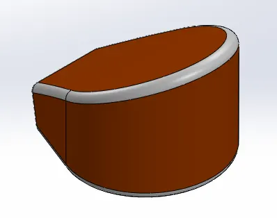
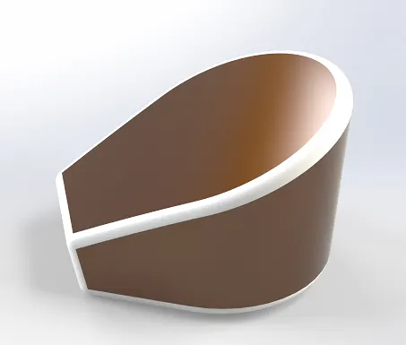
An oil tank is used to store fuel. It takes into account safety rules, preserves the environment, and prevents emissions. It is located at a particular location such that if there is an accident happens the oil tank would not burst.
Features/Commands used to create Oil Tank:
- 2-D Sketch
- Extrude Boss
- Fillet
- Shell
- Combine-- The common function allows you to add two bodies together and keep the area that is common to them.
Design Methodology:
Create a 2-D sketch in the selected plan—then use extrude boss/base to create a 3-D model—then use the combine feature to combine the bodies—then use the fillet command to fillet at the desired location—use the shell command to create the inner part of the oil tank.
Image of the modelled part:
Chain:
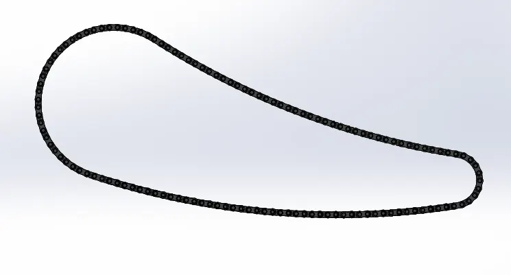
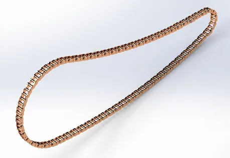
The chain is used to transmit driving power to the bike’s rear wheel. Most bike chains are made from carbon steel, but some are nickel-plated to prevent rust, or simply for aesthetics.
Features/Commands used to create Chain:
- 2-D Sketch
- Slot—It is a command to create a narrow opening or groove.
- Creating block—It uses to create a block that helps to use the same design again and again.
- Extrude Boss
- Fillet
- Curve pattern--The Curve Driven Pattern tool allows you to create patterns along a planar or 3D curve.
- Delete bodies—It is used to keep or delete bodies.
- Mirror—It is used to create a copy of a feature, (or multiple features), mirrored about a face or a plane.
Design Methodology:
Create a 2-D sketch in the selected plan—then uses the boss extrude command to create a 3-D object—then create a slot and create a block of it—use the extrude boss/ base command to create a 3-D of the slot—use curve driven pattern to create multiple objects of the same 3-D object then use the fillet command to give fillet in the required position—delete the extra bodies if needed—use the mirror command to create the full model of the chain.
Image of modelled part:
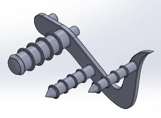
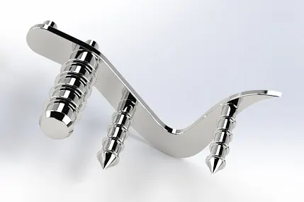
Pedal:
The pedal is located on the left side of most motorbikes just ahead o the footrest. The pedal also helps to rest the rider’s feet and also helps to maintain balance.
Features/Commands used to create Pedal:
- 2-D Sketch
- Extrude Boss
- Fillet
- Revolve
- Linear pattern-- Linear pattern is used to create multiple instances of one or more features that you can space uniformly along one or two linear paths.
- Dome
Design Methodology:
Create 2-D sketches in the selected planes—then extrude the drawing to create to make the 3-D object—then use fillet in the desired location—then use the dome command to create a domed surface in the pedal at the desired location—then for keeping your feet on the pedal some design geometry is made using boss extrude, fillet and linear pattern command.
Image of the modelled part:
Front Fork:
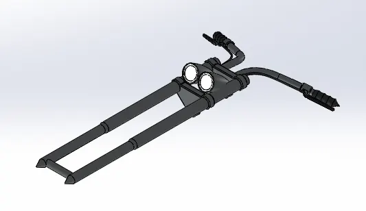
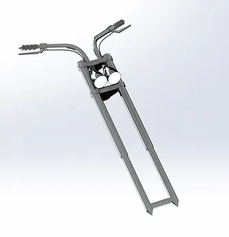
The front fork is a suspension that is held at the front of a motorbike. In nearly every motorcycle available today, the front wheel is held on by an axle that’s connected to the fork. The purpose of using a fork is to keep the tyre in contact with the road under varying conditions such as bumps, acceleration, braking, and cornering. The fork and its attachment points on the frame establish the critical geometric parameters of rake and trail, which play a major role in defining how a motorbike handles and dives during braking.
When the fork compresses, oil forces apart the spring-loaded valve on one side. This side gives compression damping. When the fork expands, oil forces apart the spring-loaded valve on the other side.
Features/Commands used to create Front Fork:
- 2-D Sketch
- Extrude Boss
- Cut Extrude
- Fillet
- Body move/ copy-- The Move/Copy Body tool takes a body, copies it, and moves it to the desired location. This will keep the required relations and the part will still be fully defined.
- Chamfer-- The chamfer tool creates a bevelled feature on selected edges, faces, or a vertex.
- Linear pattern
- Dome
- Combine
Design Methodology:
Create 2-D sketches in the selected planes—then use boss extrude and cut extrude to get the desired 3-D model—then make a composite curve to get 3-D objects at the desired location in the fork design—then use revolve and sweep command for making the handle—give fillet and chamfer to the desired location—finally give the appearances on the front fork parts.
Image of the modelled part:
Wheels:
Wheels are made to cope with radial and axial forces. They also provide a way of mounting other critical components such as the brakes, final drive and suspension. There are two wheels present in a bike. One, which is placed at the front side of the bike is called the front wheel and the other which is present at the rear end of the bike is called the rear wheel.
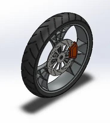
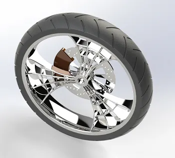
Front Wheel:
The front wheel is present on the front side of the bike. There are four components in the front wheel-
- Rim – It is the outer edge of a wheel, holding the tyre. It makes the outer circular region of the wheel on which the inside edge of the tyre is mounted.
- Rotor- It is a key part of the wheel brake system, rotors are the larger metal discs that are inside of the wheel. It is a disc-type thing connected to the tyre hub that is used in a disc brake assembly.
- Caliper-A caliper is a part of the disc brake system. Its job is to slow the vehicle’s wheel by creating friction with the brake rotors.
- Tyre- It is a thick rubber ring that is often filled with air. It is fitted around the outer edge of the wheel of a vehicle, allowing the vehicle to stick to the road surface and to travel over the ground more easily.
Features/Commands used to create Front Wheel:
- 2-D Sketch
- Extrude Boss
- Cut Extrude
- Circular pattern--Circular pattern is used to create multiple instances of one or more features that you can space uniformly around an axis.
- Fillet
- Chamfer
- Combine
Design Methodology:
Create 2-D sketches in the selected planes—then use revolve, boss extrude, cut extrude and circular pattern to make the spider-web-designed rim for the front wheel—again use these commands accordingly to make the rotor design—use the combine command to make the solid body—use the revolve command to make the tyre interface—then use the cut extrude, fillet and circular pattern option to make the pattern in the surface of the front wheel tyre.
Image of the modelled part:
Rear Wheel:
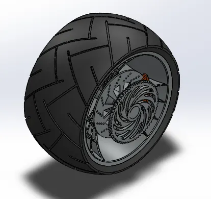
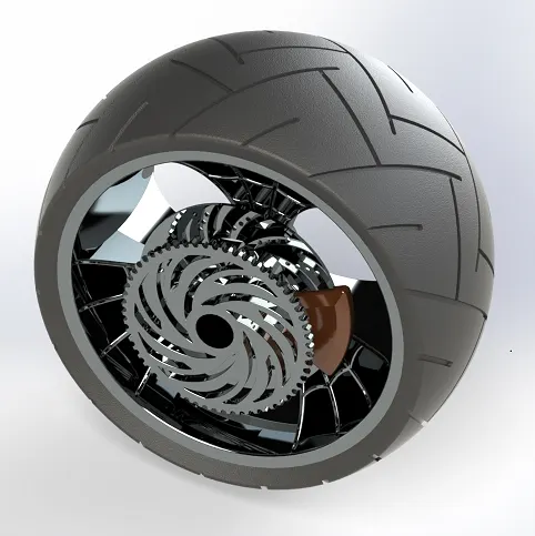
The rear wheel is present on the back side of the bike. There are five components in the rear wheel-
- Rim
- Rotor
- Caliper
- Sprocket
- Tyre
The rim, rotor, caliper, and tyre are already explained while talking about front-wheel components. Their functions are almost the same but differ in dimensions. Now, a sprocket is a part that engages the links of a chain or accurately pitched blocks on a cable.
Features/Commands used to create Rear Wheel:
- 2-D Sketch
- Extrude Boss
- Revolve
- Cut Extrude
- Circular pattern
- Fillet
- Chamfer
- Combine
Design Methodology:
Create 2-D sketches in the selected planes—then use revolve, boss extrude, cut extrude and circular pattern to make the spider-web-designed rim for the front wheel—again use these commands accordingly to make the rotor design—use the combine command to make the solid body—use the revolve command to make the tyre interface—then use the cut extrude, fillet and circular pattern option to make the pattern in the surface of the rear wheel tyre.
Image of the modelled part:
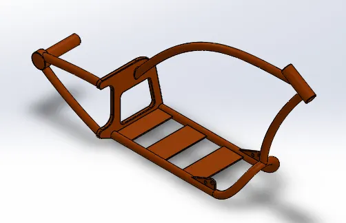
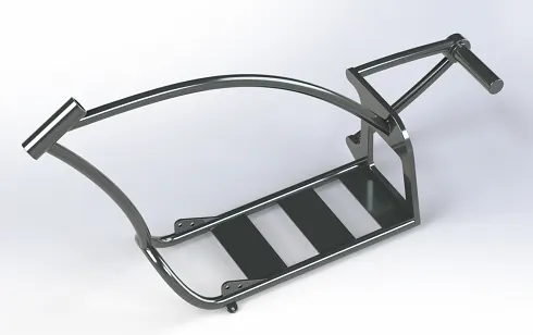
Chassis:
The chassis is the skeleton of the bike. It is often made of materials highly resistant to torsional and tensile forces such as steel. All the components of a bike like suspension, wheel, fuel tank, seats, handlebars etc, are attached to this base structure which lends a motorcycle its strength and ability to handle well.
Features/Commands used to create Chassis:
- 2-D Sketch
- Extrude Boss
- Revolve
- Cut Extrude
- Mirror—Using this feature we can mirror any feature or body.
- Fillet
- Chamfer
- Combine
- Sweep—a sweep is a tool that creates a solid, a cut or a surface feature by moving a profile along a path. To create a solid, use the Swept Boss tool to move a profile along a path. The profile can contain one or more closed contours.
- Split—The Split feature is used to create multiple parts from an existing part. One can create separate part files and form an assembly from the new parts.
Design Methodology:
Create 2-D sketches in the selected planes—use boss extrude, cut extrude, mirror, and fillet to make a 3-D model of the chassis—use combine command to make a solid body—use split command to cut the inner portion of some pipe-like structure present in the chassis-finally give the appearances to the chassis.
Image of the modelled part:
Engine:
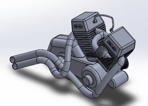
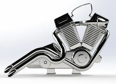
The engine is the part of a bike that powers the bike. Engines are typically two-stroke and four-stroke internal combustion engines. Most bikes use Internal Combustion Spark Ignition Engines. In the case of two strokes internal combustion engine, the process includes two strokes named Compression stroke and Power stroke. There may be different construction of engines based on application. Like, the engines with more cylinders for the same displacement feel smoother to ride and engines with fewer cylinders are cheaper, lighter, and easier to maintain.
Features/Commands used to create Engine:
- 2-D Sketch
- Extrude Boss
- Revolve
- Circular pattern
- Sweep
- Cut Extrude
- Mirror
- Fillet
- Chamfer
- Combine
- Split
Design Methodology:
Create 2-D sketches in the selected planes—use revolve, extrude boss to create the base part of the engine—use sweep command to make the intake pipe and outlet pipe of fuel and gas –again use sweep, split, fillet and chamfer to make the other parts of the engine one by one.
Image of the modelled part:
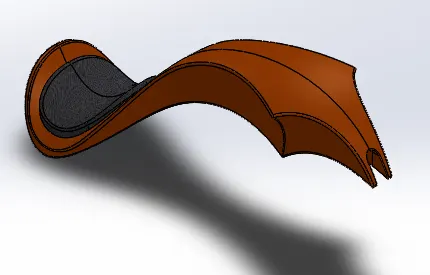
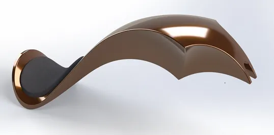
Gas Tank:
A gas tank is a safe container for inflammable fluids. The fuel is supplied to the engine part from here. Gas tank ranges in size and complexity for different purposes.
Features/Commands used to create Gas Tank:
- 2-D Sketch
- Surface sweep—Surface sweep is used to create surfaces that are generated from a section curve positioned along a path. Various Sweep types are available to extend the sweep definition as follows: Sweep by Two Guide Curves is defined as moving and adjusting a section curve along two guide curves.
- Surface trim-- Create two or more surfaces that intersect at one or more points or create a surface that intersects with a plane or has a sketch on its face.
- Surface loft-- The surface loft feature creates a shape by making transitions between multiple profiles and guide curves. This tool is very valuable for modeling complex surfaces.
- Boundary surface-- The boundary surface feature lets you create surfaces that can be tangent or curvature continuous in both directions (all sides of the surface). In most cases, this delivers a higher quality result than the loft tool.
- Surface knit—The Knit Surface tool is used to combine two or more faces and surfaces into one.
- Cut sweep-- Swept cut is a features tool, mainly used to cut a solid model or part by sweeping a completely closed profile along an open or closed path.
- Mirror
- Split line-- The Split Line tool projects an entity (sketch, solid, surface, face, plane, or surface spline) to surfaces or curved or planar faces. It divides a selected face into multiple separate faces.
- Fillet
- Shell
Design Methodology:
Create 2-D sketches in the selected planes—use sweep command to make a 3-D from the 2-D sketch—cut the extra portion of the swept object—use surface loft boundary surface to make the other parts of the Gas Tank—use boundary surface option to make the seat over the gas tank at a perfect position—use the surface knit feature to add the surfaces made earlier—now create a hollow portion inside the gas tank to store the gas –finally give fillet in the desired location –give the appearance to it and finalize the model.
Image of the modelled part:
What is an Assembly?
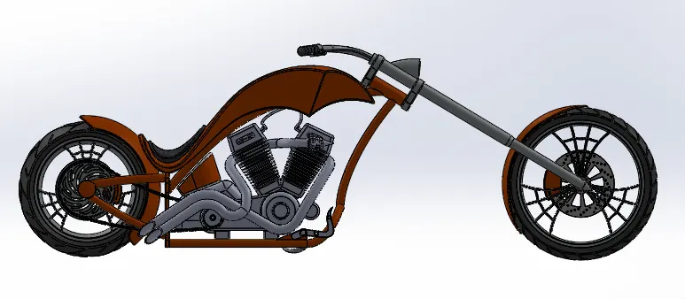
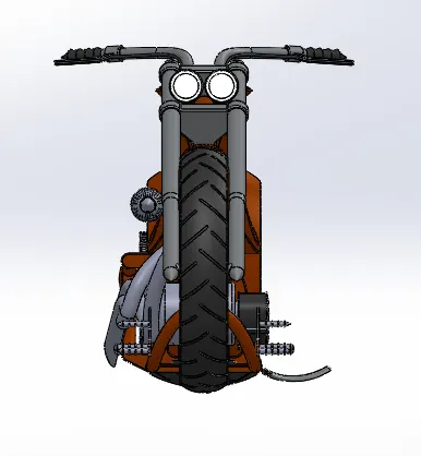
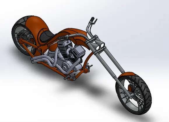
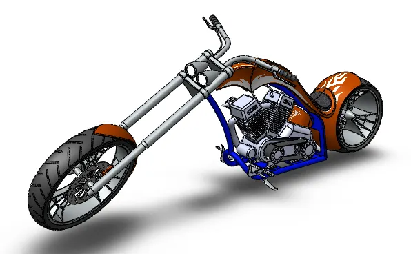
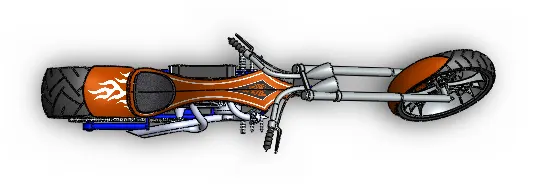
An assembly is a document where all the parts, features and sub-assemblies are mated together. Here all the parts of the chopper are inserted one by one and mate with the chassis using manual mates. After the assembly, the bike is fully ready for rendering.
Methodology:
Import the chassis part first and fix it—then import the other parts one by one—then give the parts appropriate mate with the chassis—finally, add decals to give it a good look.
Image of the modelled assembly of the chopper:
Photorealistic rendering:
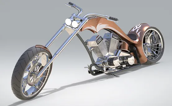
It is a digital process using a 3-D CAD model within a software package to create a digital image of the model. The result is a rendering image that is hard to distinguish from a photograph of a real-life object.
Methodology:
Make a camera view of the chopper inside the assembly—then save it—now open Solidworks visualize software to give it a proper rendering—Inside the Solidworks visualize environment—now to give a proper rendering we have to give the parts of the bike a glowing appearance according to the HDR environment –then go for the output procedure of rendering and render the part perfectly.
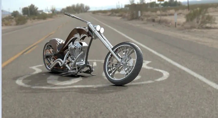
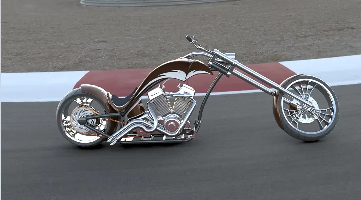
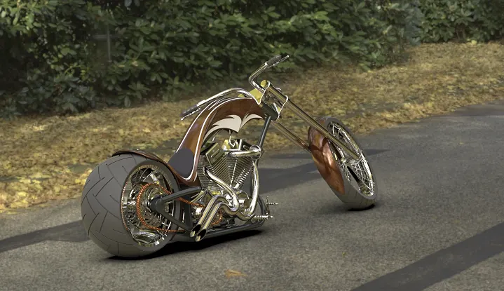
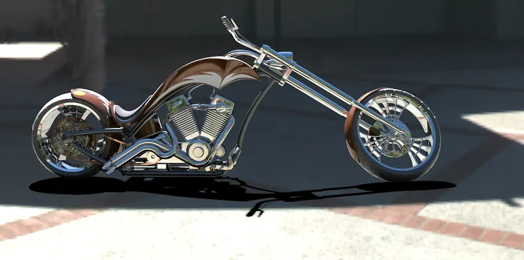
Image of the rendered model of an American chopper in different environments:
Default environment:
Root-66 environment:
Race track environment:
Fall street environment:
Villa interior environment:
Conclusion:
All the parts are modelled individually in the Solidworks part environment and then assembled to make the chopper model. Then solid work visualize is used to give the model a good rendering and a real-life view.