Wiring harness design in CATIA V5 - 3D modeling Week 4 Challenge
REPORT ON WEEK 4 CHALLENGE
Objective:
The objective of the report is—
- Define the connectors properly one by one.
- Route the wires and connect the connectors.
- Apply the protection covering to the routed wires.
Defining the connectors:
First, the connectors should be defined electrically. Necessary points and axis systems are made on every connector in the Part Design workbench. Then connector is electrically defined in the Electrical part design workbench. Then the bundle entry point and connector connection point are made on the connector using certain commands.
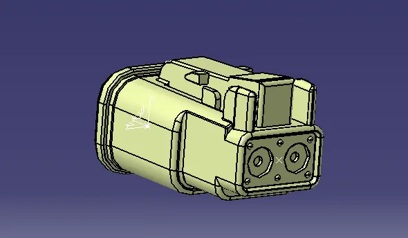
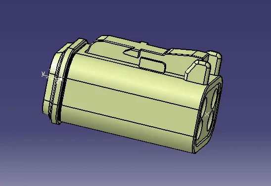
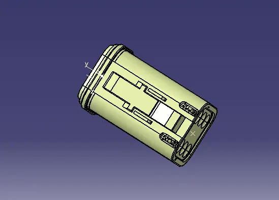
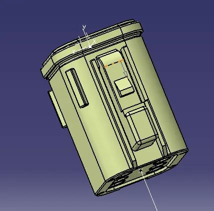
Image of the modelled parts:
Finalize the assembly:
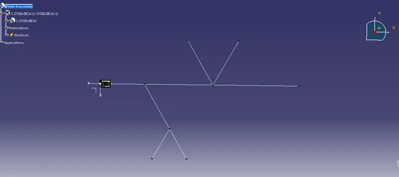
All the electrically defined products are then opened in the assembly workbench. Select one connector then opened it in the part design workbench. Then create the lines as per the given data.
Now, adjust all the connector's positions by using different commands like snaps, smart move, manipulation or by using compass.
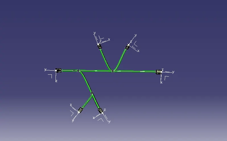
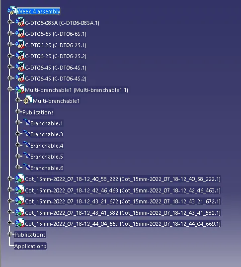
Then move to the electrical harness assembly workbench. Then use the Geometric bundle command and select the body to define. Then use the multi-branchable command and give the diameter of the wire and use the 1.5:1 ratio for the bent radius. Then go to the bundle definition option and select two connectors, and select the required tangent direction for the routing of wiring.
Now, to create the side branches we need to use the add a branch point command and then select the exact location of the branch point by selecting the length or the ratio. Thus, the main branch will be divided accordingly. Again, use the bundle definition command to rout the wires to the other connectors.
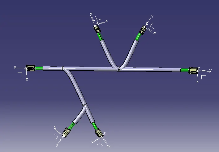
Now, exit from the multi-branchable and return to the main geometrical part. Then, use the protection covering option to give the cot tubes of proper diameter to the routed wires. For giving the cot tube, use the protection covering command and then navigate to the cot tube catalogue which is created earlier. Then select the proper diameter of the cot tube and select the start extremity and end extremity as required. Thus, the routing is completed and saved with all the changes.
Image of the modelled part:
Conclusion:
All the connectors are defined with the bundle entry point and connector connection point. And then, connectors are connected with the wires. And also, protective covering is added to the routed wires. The full process is completed using Catia V5 software using different workbenches.