Wiring harness routing & packaging Rules Week 3 Challenge
Report on wiring harness weak 3 challenge:
Objective:
- To define the clamp as an electrical support and define bundle entry and exit point and plane.
- To define Back shell for the connectors and add properties like bundle connection point back shell connection point.
- To make cotter tubes of different sizes and save them in a catalogue.
Introduction:
All the parts are defined in Catia V5 environments using suitable workbenches and commands. The full procedure is done using the following steps—
Define the P- clamp:
Creating point:
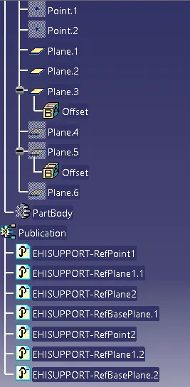
In part design workbench we have to create entry and exit point of bundle in the P-clamp. For that we have to use point command and to select suitable geometry to make the points.
Creating planes:
So, for the clamps we have to define entry, exit and base planes. For that, we have to use part design workbench. In this workbench, use the plane command and select the parallel through point option and select the outer surface of the clip in reference and select the entry point which is earlier created. With this we will get entry plane. Follow the same procedure for the exit plane too. For the base plane, we have to click on the base surface and click on offset from surface command.
Define as an electrical support part:
After creating necessary points and planes, we have to move to Electrical part design workbench. Here, we have to select define support part command and then have to select the P-clamp. Then we have to define entry and exit side of the P-clamp. For that, we have to select the entry point and entry plane in the first plane definition option, then we have to select exit plane in the second plane definition option and have to select the base plane in the base plane definition option. As we know that the clamp can be added in any side so we have to make it versatile for the opposite direction too. So, follow the same procedure to define the entry and exit side of the P-clamp from the opposite side. Finally, save all the changes and the P-clamp is fully defined now.
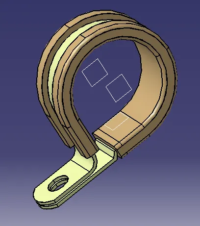
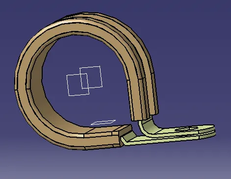
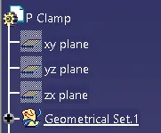
Image of the modelled part:
Define the Back shell:
Creating point:
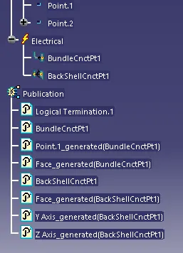
In the part design workbench we have to create bundle entry point and back shell connection point for the back shell part. So, use the point command and select the suitable geometry for the bundle connection point and for the back shell connection point.
Creating axis:
We have to defined axis system for the back shell connection. So, for that use the axis command and select the back shell connection point which has been created earlier. Rotate the axis such a way that Y-axis is facing towards the mating face of the connector and Z-axis toward the top of the back shell.
Define the back shell as electrical part:
Move to Electrical part design workbench and select the define back shell command and then select the back shell body. Thus, it will be defined the back shell.
Define the bundle connection point:
Use the define bundle connection point command and select the body and then select the bundle entry face as representation, then select the bundle entry point, and again select the bundle entry face as initial condition.
Define the back shell connection point:
Use the define back shell connection point command and select the body. Then, select the point which was made earlier for the representation. Then select the mating face for the contact option. Select the Y-axis for the coincidence and then select the Z-axis for the orientation.
Finally save all the changes. Thus we have fully defined the back shell and it is ready to use.
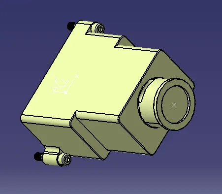
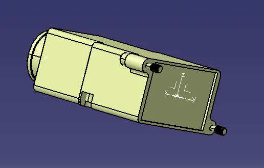
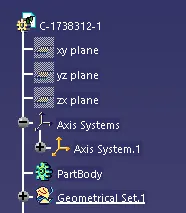
Image of the modelled part:
Creating Corrugated tubes:
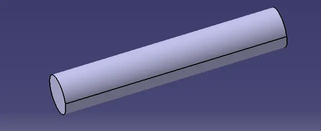
Create a new part in the Catia V5 environment and move to the Electrical part design workbench. Use the define protection part command and select the part body option. Then change the name to cot tube and select corrugated tube in the type section. Change the inner diameter to the desired value and change the thickness accordingly. And in the bend radius option give the bend radius which is 1.5 times the outer radius of the corrugated tube.
In this way make different-sized corrugated tubes.
Image of the modelled part:
Cot tube _5mm
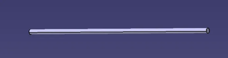
Cot tube 10mm
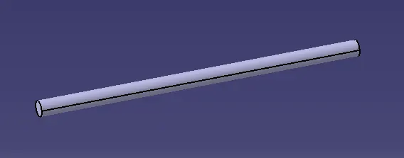
Cot tube 15mm
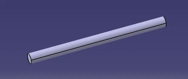
Cot tube 20mm
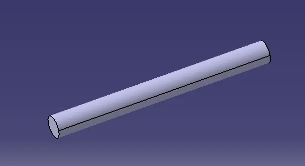
Cot tube 35mm
Creating a new catalogue and saving the corrugated tubes:
Use the new catalogue document command and select the add family option. Then, give any name to the family and select the conduit as the type for the corrugated tubes. Then move to each corrugated tube part and select the store device command then at the catalogue section brows to the catalogue made for the corrugated tubes. Then select the name of the family then save it in the catalogue.
Conclusion:
Thus, I have defined the clamp and back shell using different workbenches in the Catia V5 environment. I have also created different-sized corrugated tubes and have saved them in the tube catalogue.