Wiring harness design in CATIA V5 - 3D modeling Week 5 & 6 Challenge
Wiring harness design in CATIA V5 - 3D modeling Week 5 & 6
Aim
Route the following harness layout in Electrical workbench. Make assumption for harness bundle diameters. Use the connectors provided. After completion of routing.
(DOWNLOAD CAD DATA)
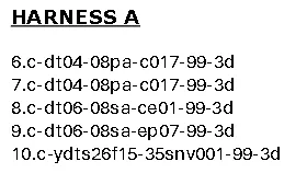
HARNESS A
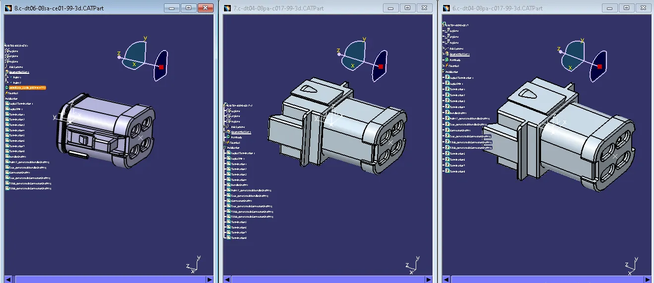
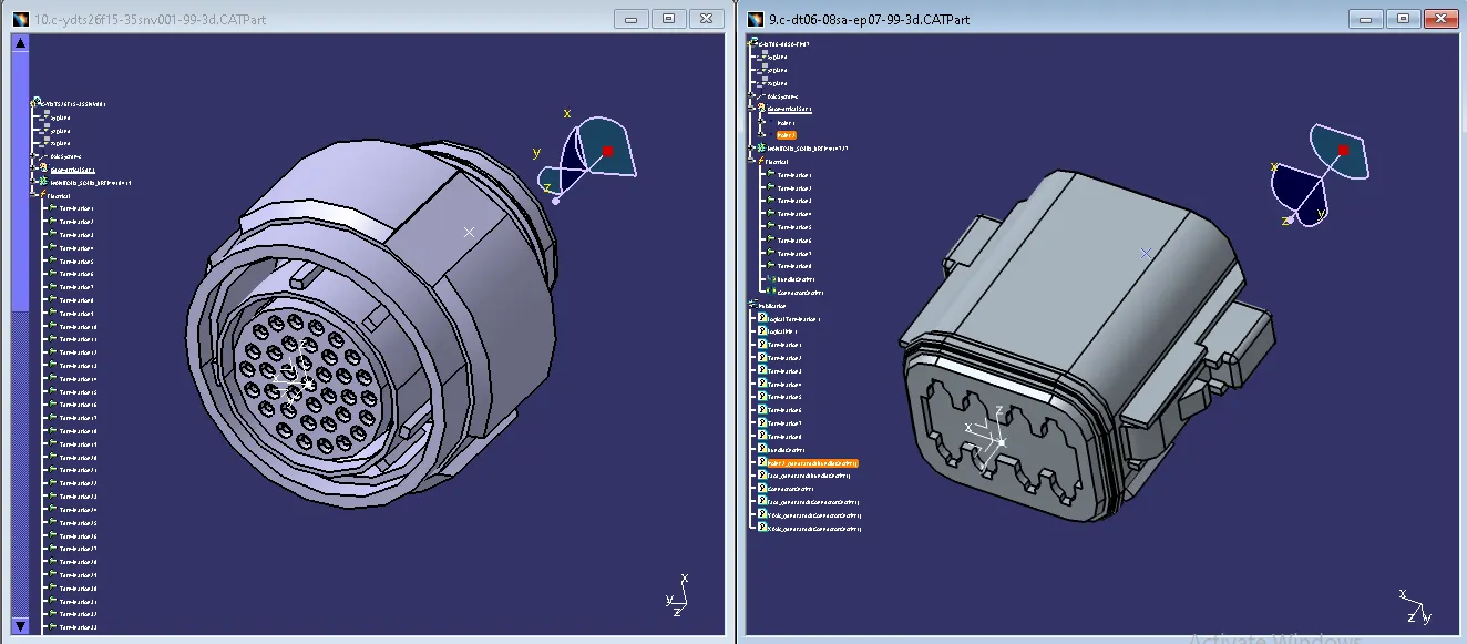
1. Create Bundle connection point, connector connection point, Axis system, for all connectors.(Part design)
2. Define connectors, Define Bundle connection point, Define connector connection point for all connectors.(Electrical part design)
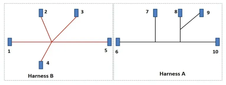
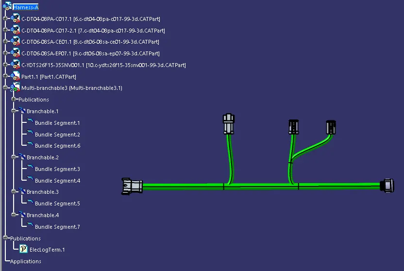
3. Arrange all connectors like Harness A Layout in (Assembly Design work bench)
4. Add Multi- branchable and connect bundles (Electrical Harness Assembly work bench)
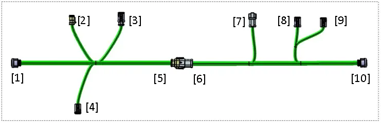
 HARNESS A ASSEMBLY
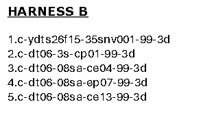
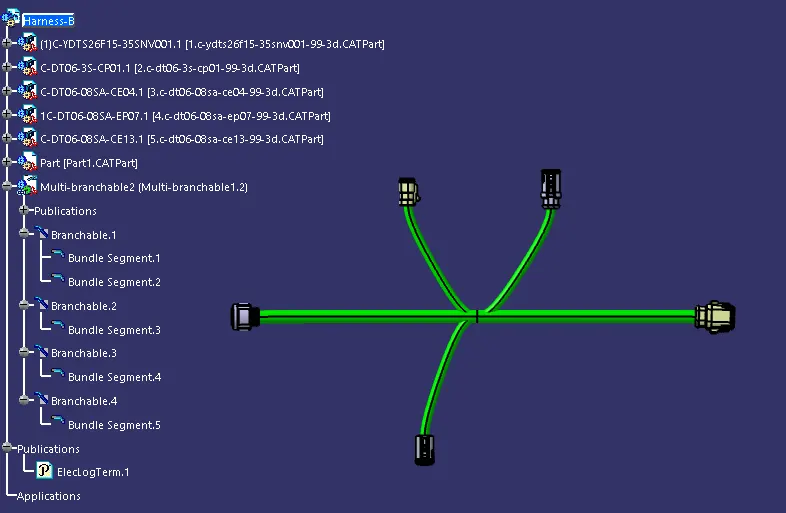
HARNESS B
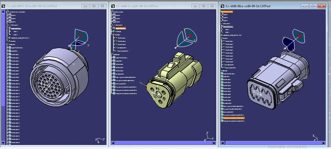
1. Create Bundle connection point, connector connection point, Axis system, for all connectors.(Part design)
2. Define connectors, Define Bundle connection point, Define connector connection point for all connectors.(Electrical part design)
3. Arrange all connectors like Harness B Layout.(Assembly Design work bench)
4. Add Multi-branchable and connect bundles (Electrical Harness Assembly work bench)
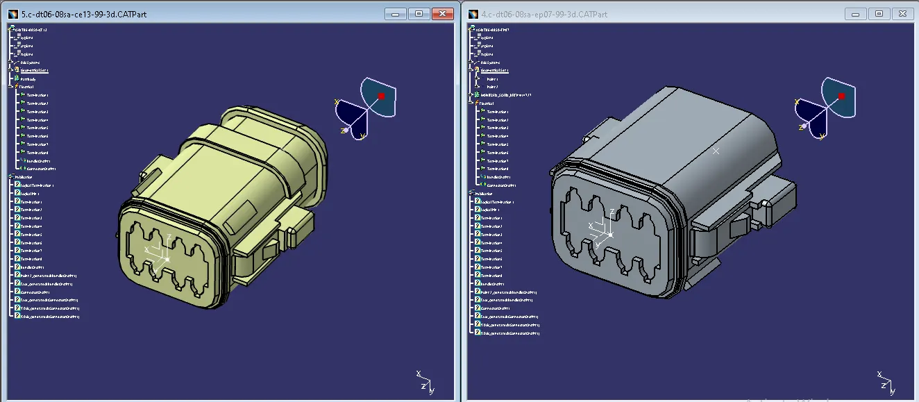
HARNESS B ASSEMBLY
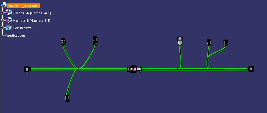
HARNESS ASSEMBLY (Electrical Assembly Design)
Create product & insert Harness A & Harness B Change work bench (Electrical Assembly Design)
Connect Harness A & Harness B (connect electrical devices)
Add annotation to all connectors.