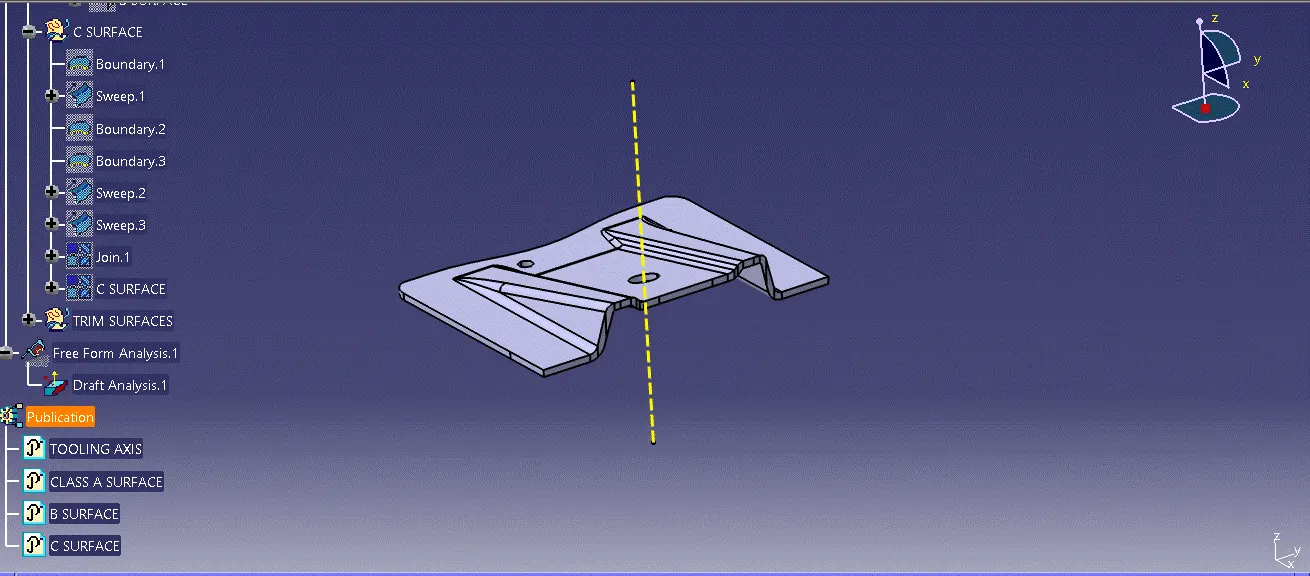
Week 9 - Challenge 1 - Base Bracket Design
Week 9 - Challenge 1 - Base Bracket Design
Aim
Creation of proper tooling axis considering the required draft angle of a component Performing draft analysis on the given Class A Surface and then final component Creation of Class B and Class C Surface
Tooling axis In the Z direction, I selected holes that are clear to create a dummy tooling axis. First, I created a point on the circle and then a line in the Z direction. To identify the bases that may cause problems, I changed their color. Next, I created a YZ plane and took an intersection with the plane, creating two points at both ends of the line. Using the Line Definition tool, I changed the line type to bisecting and selected two lines to create the main tooling axis.
I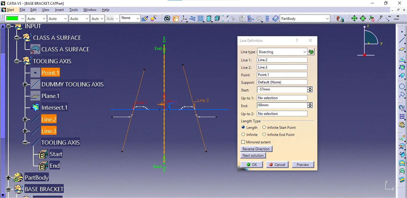
Draft analysis
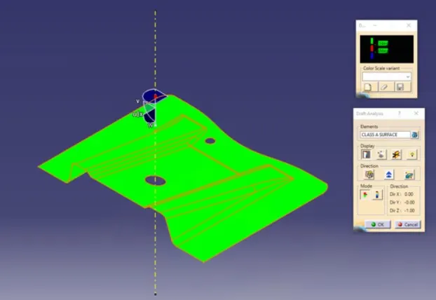
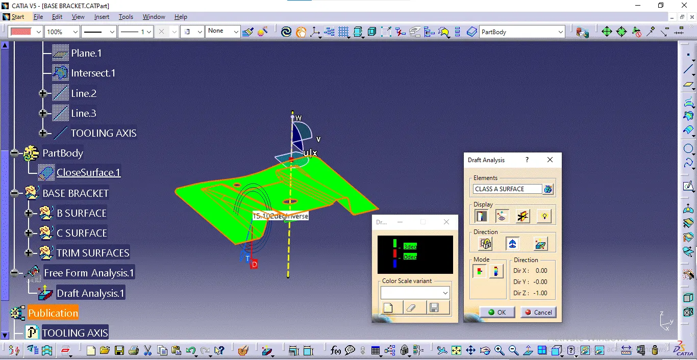
To perform draft analysis, click Insert > Analysis > Feature Draft Analysis. Open the Draft Analysis toolbar, go to the display block, and select Analysis under the Running Point to check angles on the Class A surface. The color scale indicates if the draft angle meets the 3-degree requirement using colors green, blue, and red. After analysis, align and fix the compass to the tooling axis by selecting Use the Compass to Define the New Current Draft Direction in the Direction block, aligning the compass with the tooling axis, and clicking the lock symbol. Finally, click OK on the Draft Analysis toolbar to complete the process.
Creating Class B Surface: Extract the Class A surfaces using multiple operations and untrim them. Ensure proper intersection with extrapolation, then trim and offset the surfaces by 2.5 mm to achieve the desired thickness. Use the trim command to remove excess material. Place the trimmed surfaces into a new geometrical set and name it accordingly. Apply fillets, adjusting the component thickness if the fillets extend beyond it, ensuring uniformity.
Creating Class C Surface: The Class C surface connects the Class A surface and the Class B surface. It is also referred to as the thickened surface, providing the necessary thickness to the designed component. Extract the boundary from the class A surface using boundary command. Use the Sweep command, select Profile Type as Line, and set the Subtype to With Draft Direction. Choose the guide curve and specify the draft direction with a draft angle of 3 degrees
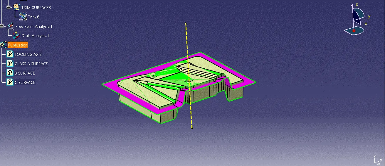
Base Bracket