Week 10 - Challenge 1- Attachment Feature Creation (Ribs & Screw Boss)
Week 10 - Challenge 1- Attachment Feature Creation(Ribs & Screw Boss)
Aim:
Design of ribs for Drill Handle following the design rules. Rib root thickness analysis should be carried out. Design of Screw Boss for Drill Handle following the design rules.
Tooling Axis:
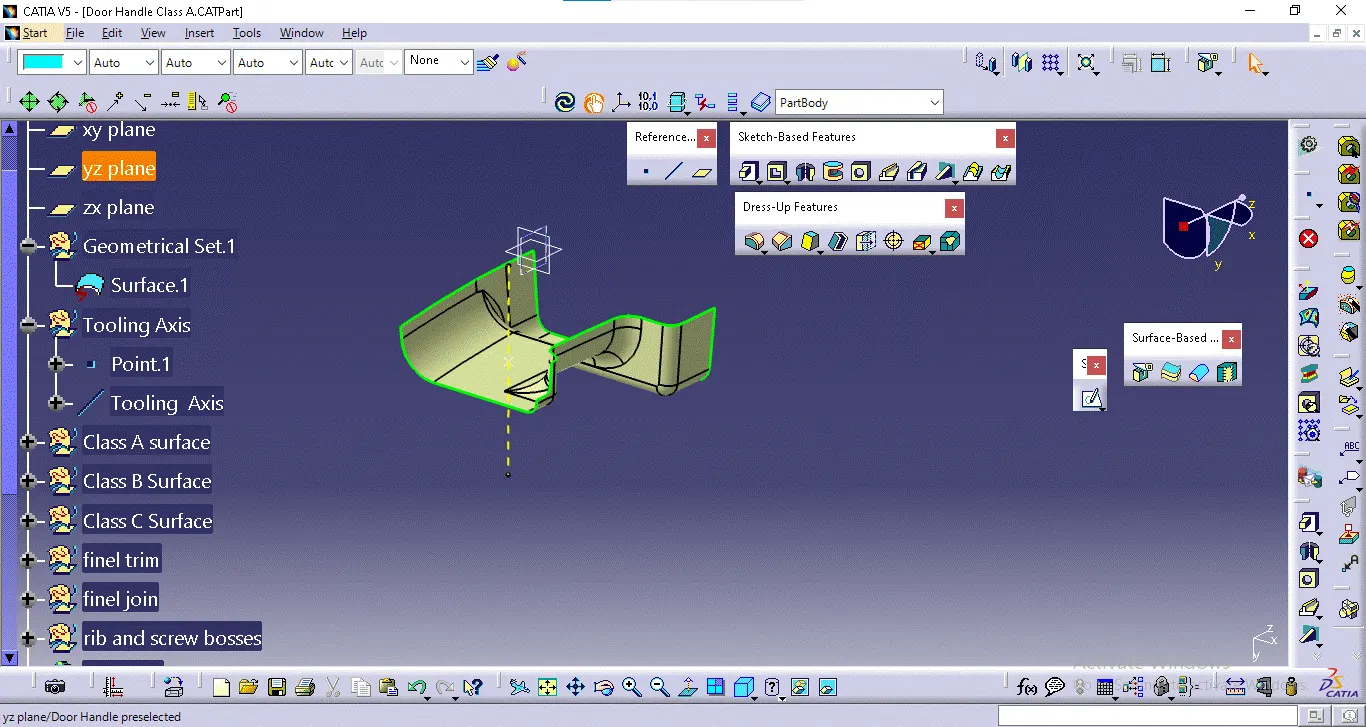
To create a tooling axis using a Class A surface, first examine the surface patches along the y-axis to identify the appropriate direction for tooling. Place a reference point in between 2 edge of the surface and then draw the tooling axis line using the "Point Direction" line type from this point create line on y direction.. This line will represent the tooling direction.
Draft analysis:
To perform draft analysis, go to Insert > Analysis > Feature Draft Analysis, and use the Draft Analysis toolbar to check angles on the Class A surface. The color scale indicates if the draft angle meets the 3-degree requirement. Align the compass with the tooling axis, lock it, and click OK to finalize the analysis.
Creating Class B Surface:
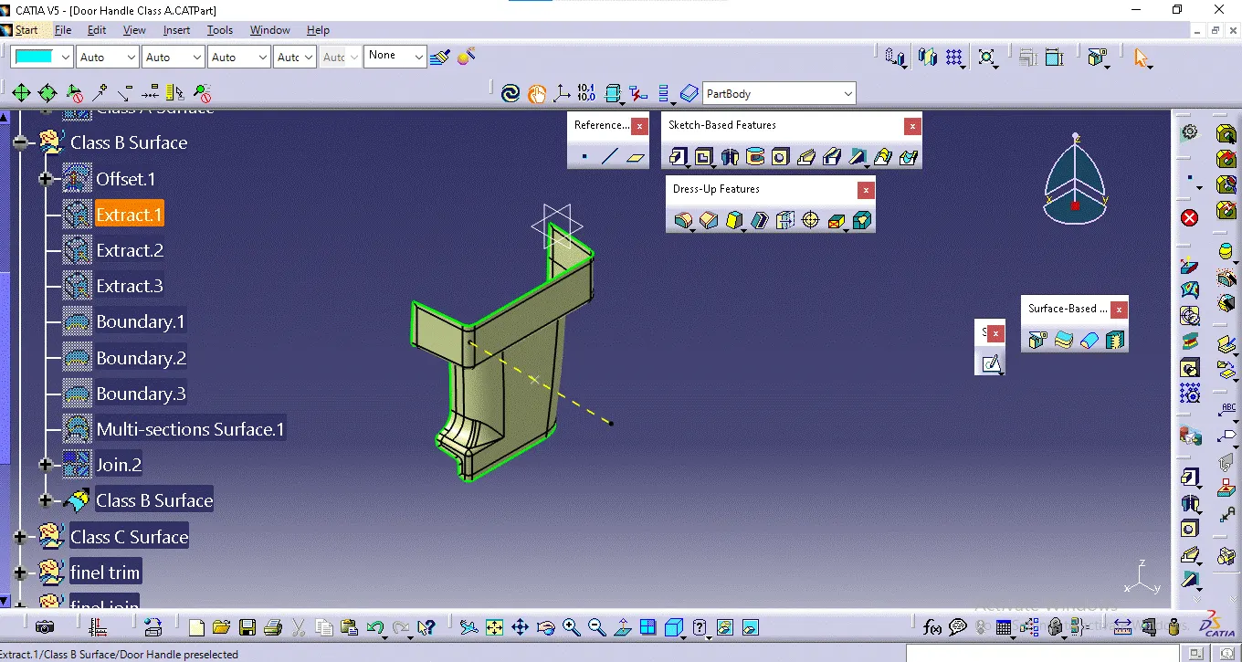
To create the Class B surface for the door handle, first, offset the Class A surface inward by 2.5mm to establish the initial Class B shape. Next, address any irregularities or patches caused by fillets on the Class A surface by applying the multi-section solid command. This command helps close the patches by defining multiple cross-sections, ensuring a smooth transition. Finally, adjust and refine the resulting Class B surface to align with the Class A surface and meet design specifications.
To address the single patch observed on the offset surface, you used the multi-section solid command to close it and create a proper Class B surface. This approach effectively fills the patch and ensures a smooth, continuous surface that aligns with the design requirements.
Creating Class C Surface:
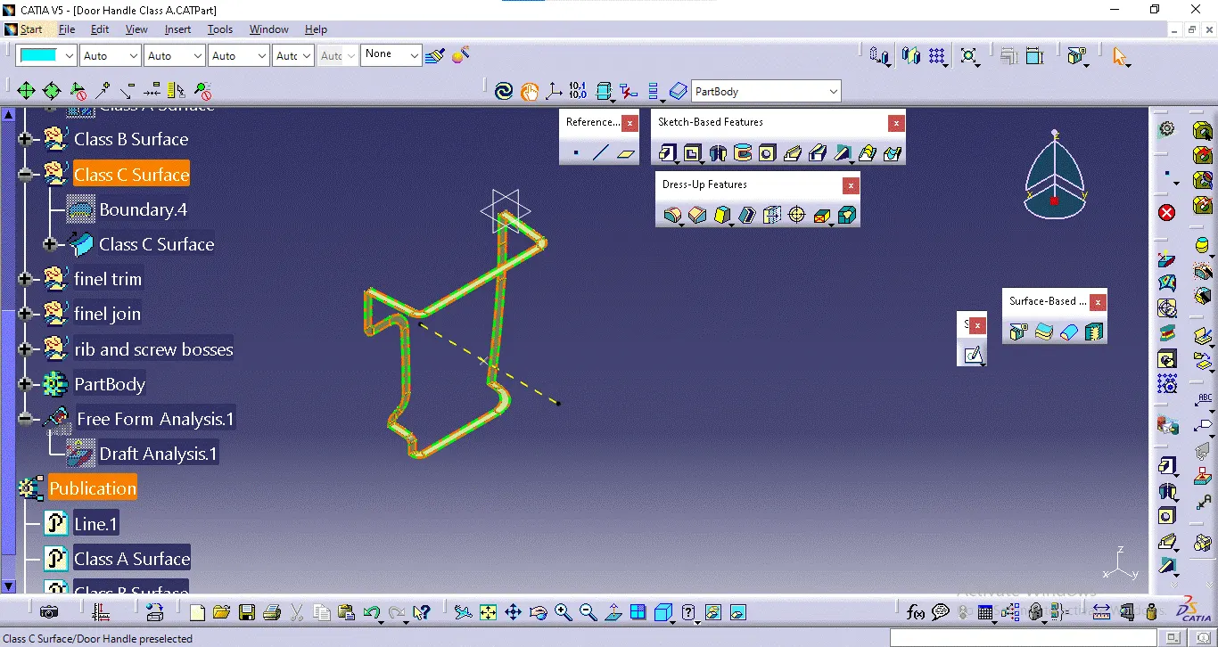
To create the Class C surface, start by referencing the Class A and Class B surfaces to define the required thickness. In the Surface Workbench, use the Sweep command, selecting the boundary of the Class A surface as the profile and aligning the sweep along the tooling axis with a 3-degree draft angle. This draft angle will be applied to the sweep and can be adjusted if design holes are needed. Once the Class C surface is generated, merge it with the Class A surface to ensure a seamless connection. Then, trim the Class B surface with the Class C surface to refine the overall shape. Finally, use the boundary command to check the alignment and precision, ensuring the Class C surface integrates smoothly and meets the required quality standards.
Engineering Features
Rib Creation
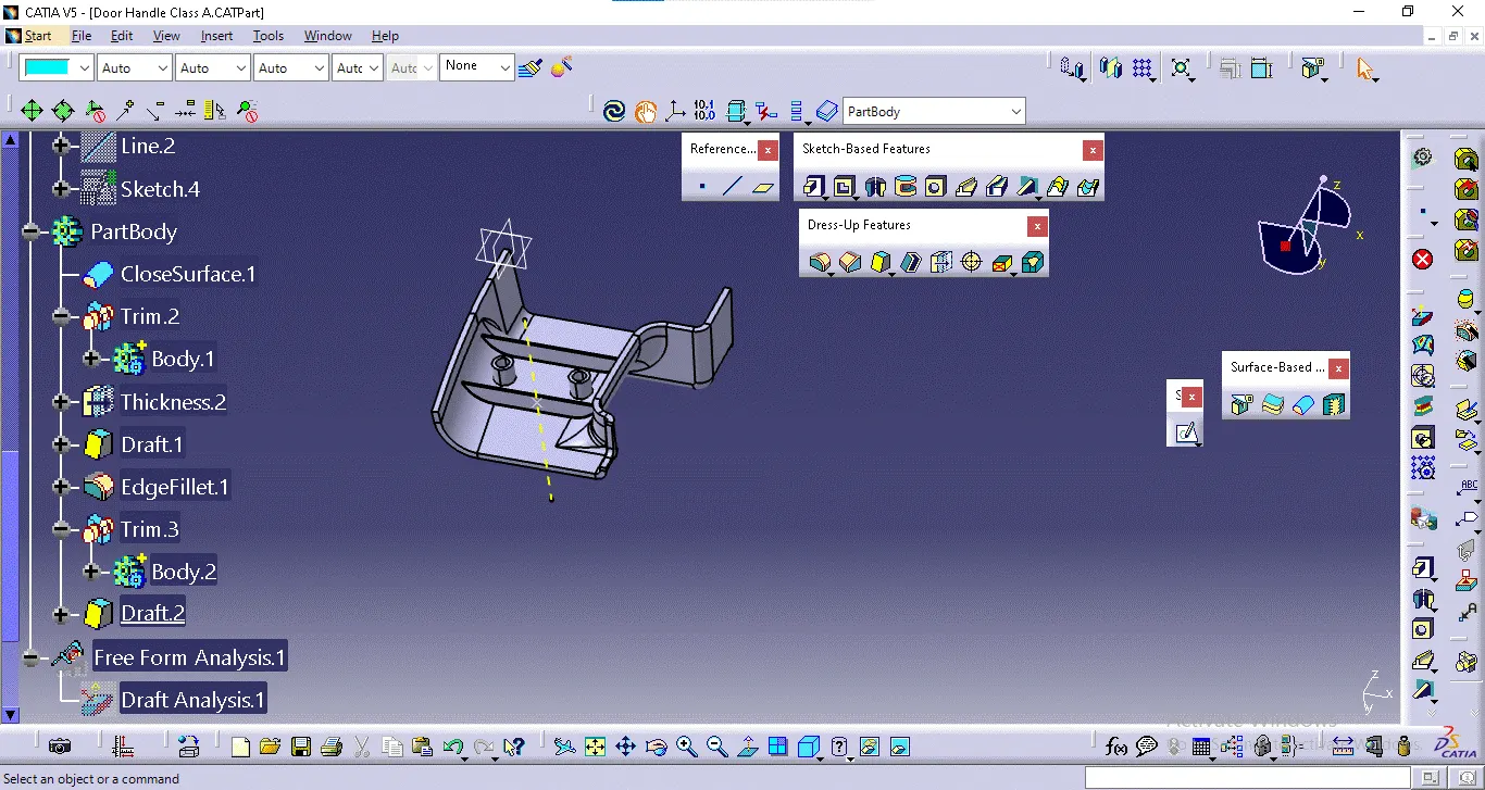
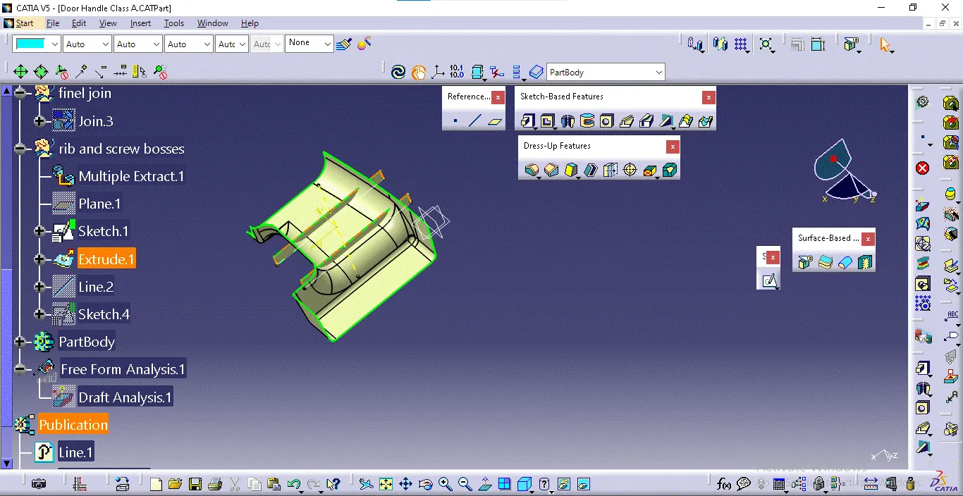
To create a rib in plastic design, start by defining the rib’s location and purpose within the part. In your design software, select the Rib tool or command, then specify the rib’s base profile and thickness. Ensure the rib is oriented correctly, usually perpendicular to the main surface, to provide maximum support and strength. Adjust the rib’s draft angle, if necessary, to facilitate easy mold release and reduce material stress. Verify that the rib’s thickness is consistent with design guidelines, typically between 0.5 mm to 3 mm, depending on the part’s size and function. Finally, check the rib’s alignment with adjacent features and ensure it integrates well with the surrounding geometry to maintain the overall structural integrity of the component.
Screw boss
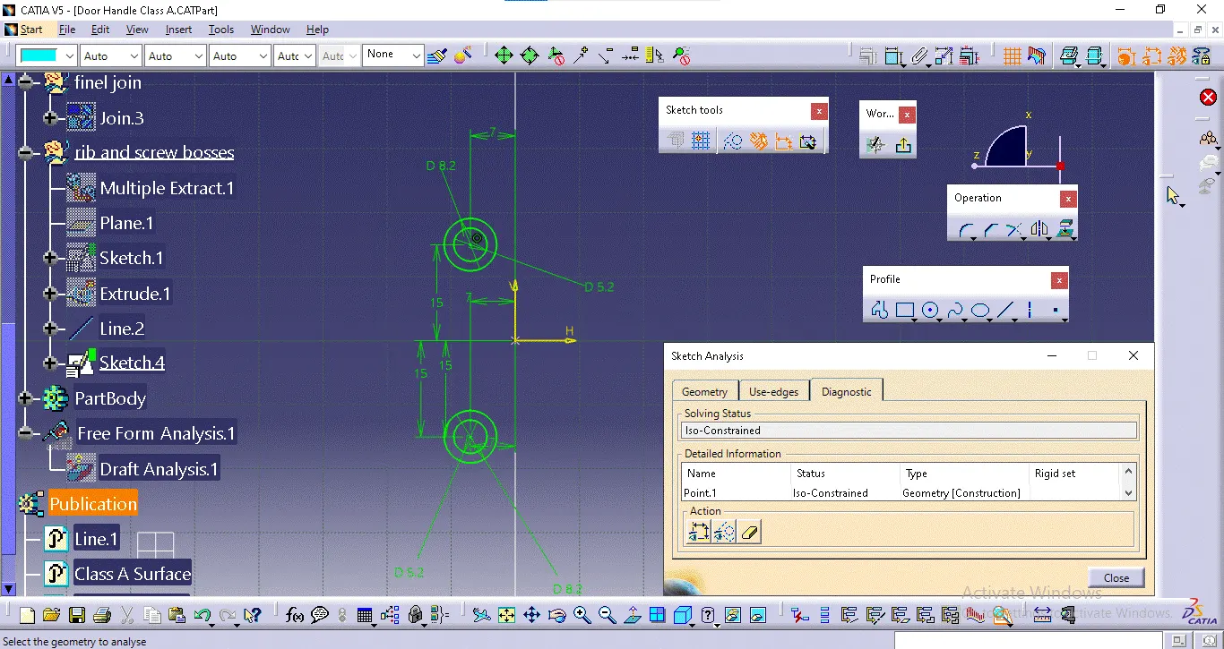
To create a screw boss in plastic design, begin by determining its location and size based on the part’s functional requirements. In your CAD software, use the Screw Boss tool or command to define the boss's diameter, height, and wall thickness. Ensure that the boss is properly aligned with the surrounding features to accommodate the screw and provide a secure fit. Incorporate a draft angle, typically between 1 to 3 degrees, to facilitate easier mold release. Add appropriate fillets or radii to the boss’s edges to reduce stress concentrations and improve durability. Finally, check the design for proper clearance and integration with other components, ensuring that the screw boss will function correctly within the assembled part.
Create the Screw boss for the Drill Handle considering the design rules
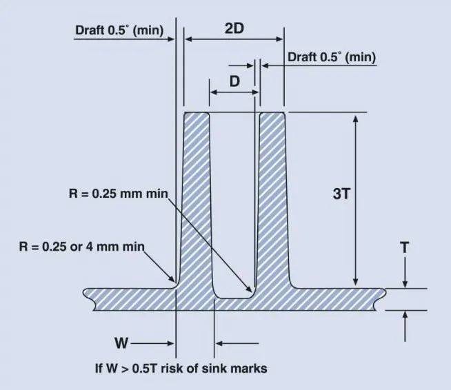
General Guidelines for Bosses:
- Draft - 0.5 degrees on the walls of boss
- Thickness - Typically 40%* of the nominal wall at the base.
- Height to Diameter Ratio - 3:1
- Radii - 0.25mm maximum radii.