Week 9 - Challenge 3 - Bumper
Week 9 - Challenge 3 - Bumper
Aim
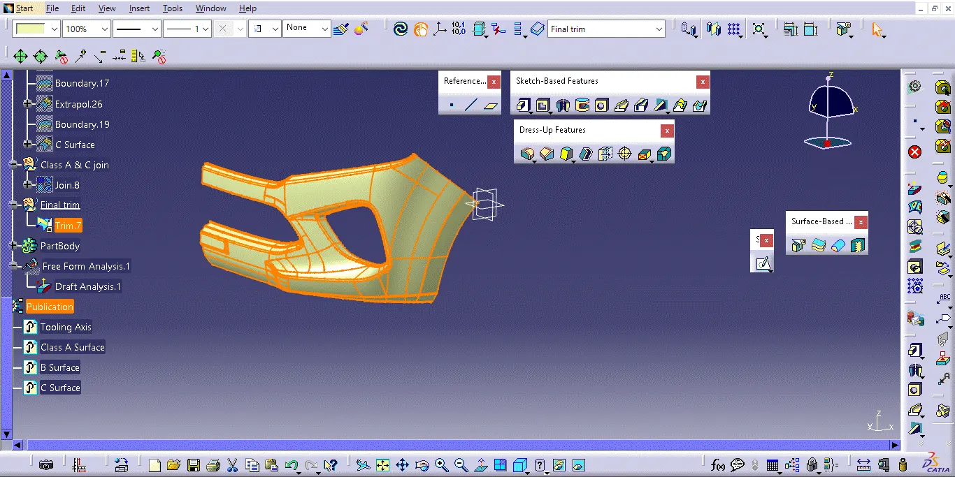
Creation of proper tooling axis considering the required draft angle of a component Performing draft analysis on the given Class A Surface and then final component Creation of Class B and Class C Surface
Tooling axis
To create the tooling axis, first determine the direction using the Class A surface. In the X direction, identify the surface patches, create a midpoint on the curve, and insert a line using the [point direction] line type. Verify the correctness of the line with a draft analysis by fixing the compass on the line and ensuring the draft analysis is clear. 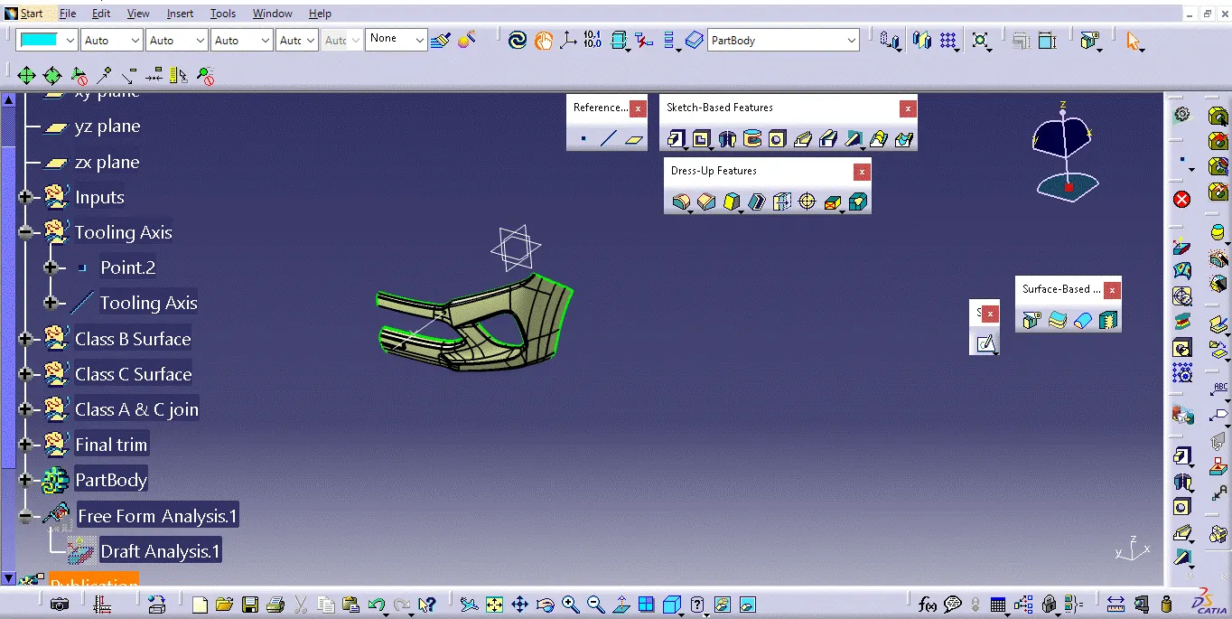
Draft analysis
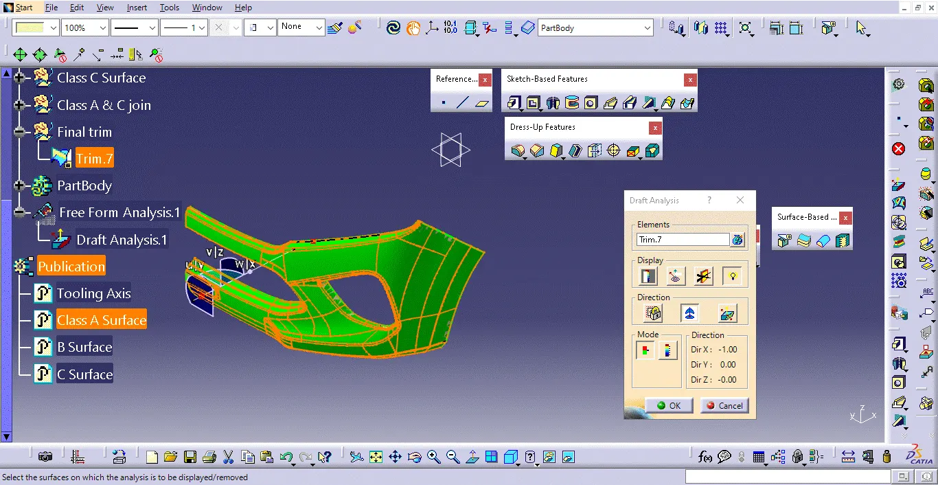
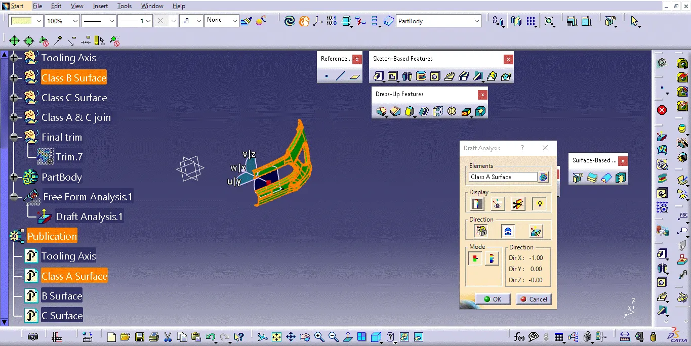
To perform draft analysis, click Insert > Analysis > Feature Draft Analysis. Open the Draft Analysis toolbar, go to the display block, and select Analysis under the Running Point to check angles on the Class A surface. The color scale indicates if the draft angle meets the 3-degree requirement using colors green, blue, and red. After analysis, align and fix the compass to the tooling axis by selecting Use the Compass to Define the New Current Draft Direction in the Direction block, aligning the compass with the tooling axis, and clicking the lock symbol. Finally, click OK on the Draft Analysis toolbar to complete the process.
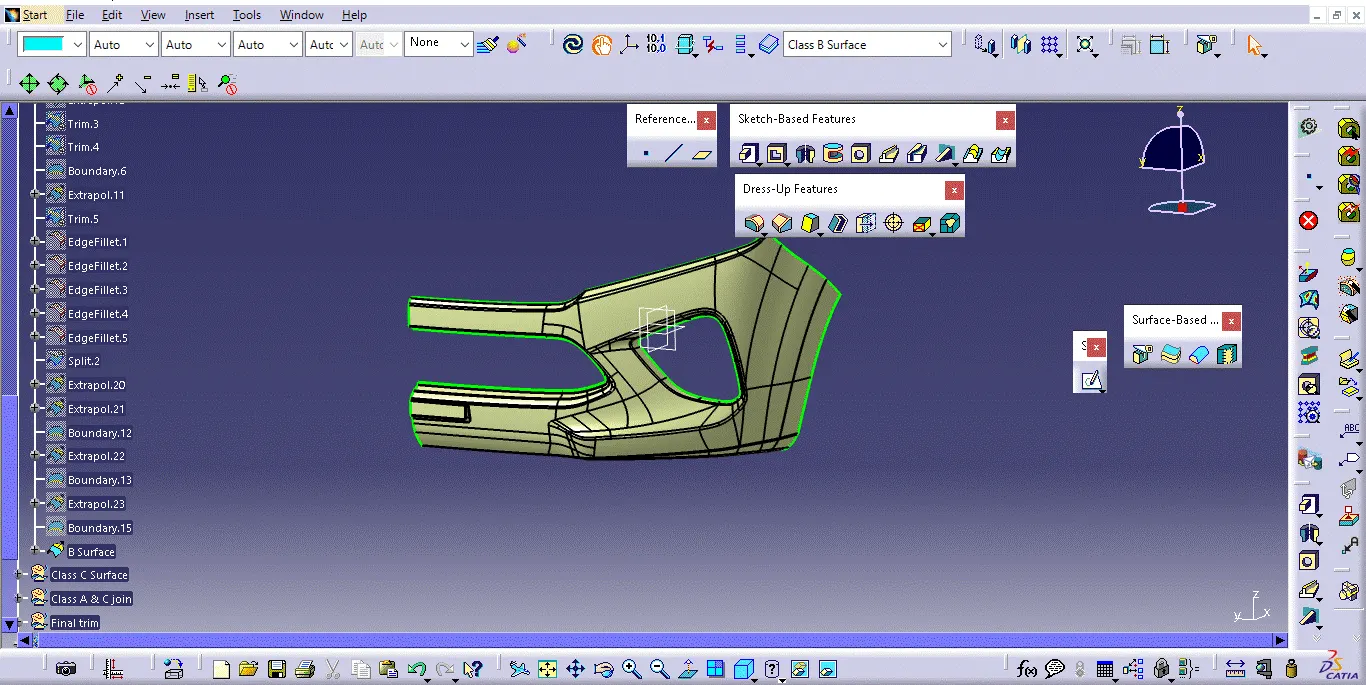
Creating Class B Surface:
Creating a Class B surface for a bumper involves designing the non-visible, structural areas that support the Class A surfaces. These surfaces ensure proper fitment, mounting, and structural integrity. The focus is on maintaining continuity and smooth transitions, considering material thickness, draft angles, and manufacturability. Class B surfaces must support efficient production and assembly while meeting engineering requirements. Final validation ensures these surfaces function correctly without compromising the Class A surfaces.
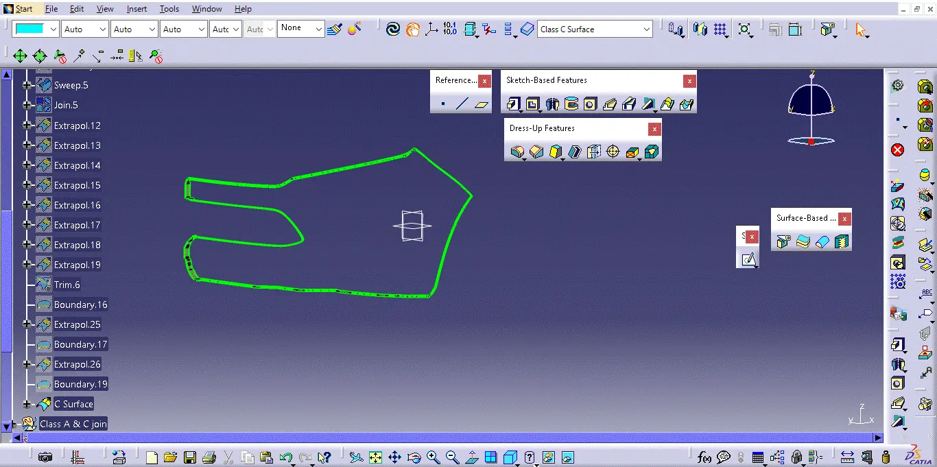
Creating Class C Surface:
Creating a Class C surface for a bumper focuses on the non-visible, internal areas that provide structural support and attachment points. These surfaces are primarily concerned with functionality rather than aesthetics and include the internal features needed for manufacturing, such as ribs, bosses, and brackets. The design ensures proper thickness, draft angles, and support for Class B surfaces, with a focus on manufacturability and assembly efficiency. Class C surfaces are less refined but crucial for the bumper's overall structural integrity and ease of production.
Bumper