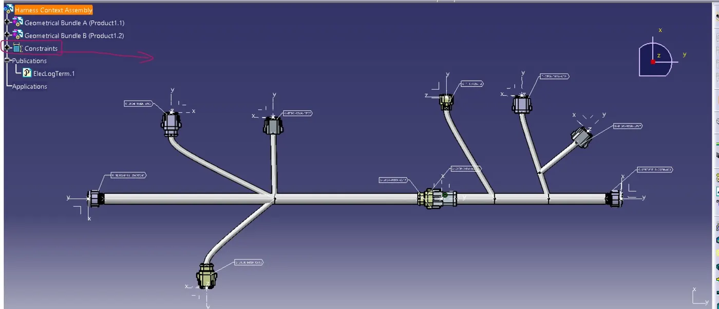
Wiring harness design in CATIA V5 - 3D modeling Week 5 & 6 Challenge
Objectives: -
1. Check Bundle Continuity
2. Add Annotation to all connectors
3. Check for bundle warning
4. Generate CAT PART and Convert it to igs format.
Steps taken while completing objectives :
Define mechanical components electrically and make catalogue:-
Ø Here downloaded all the required components from te.com and then defines them electrically
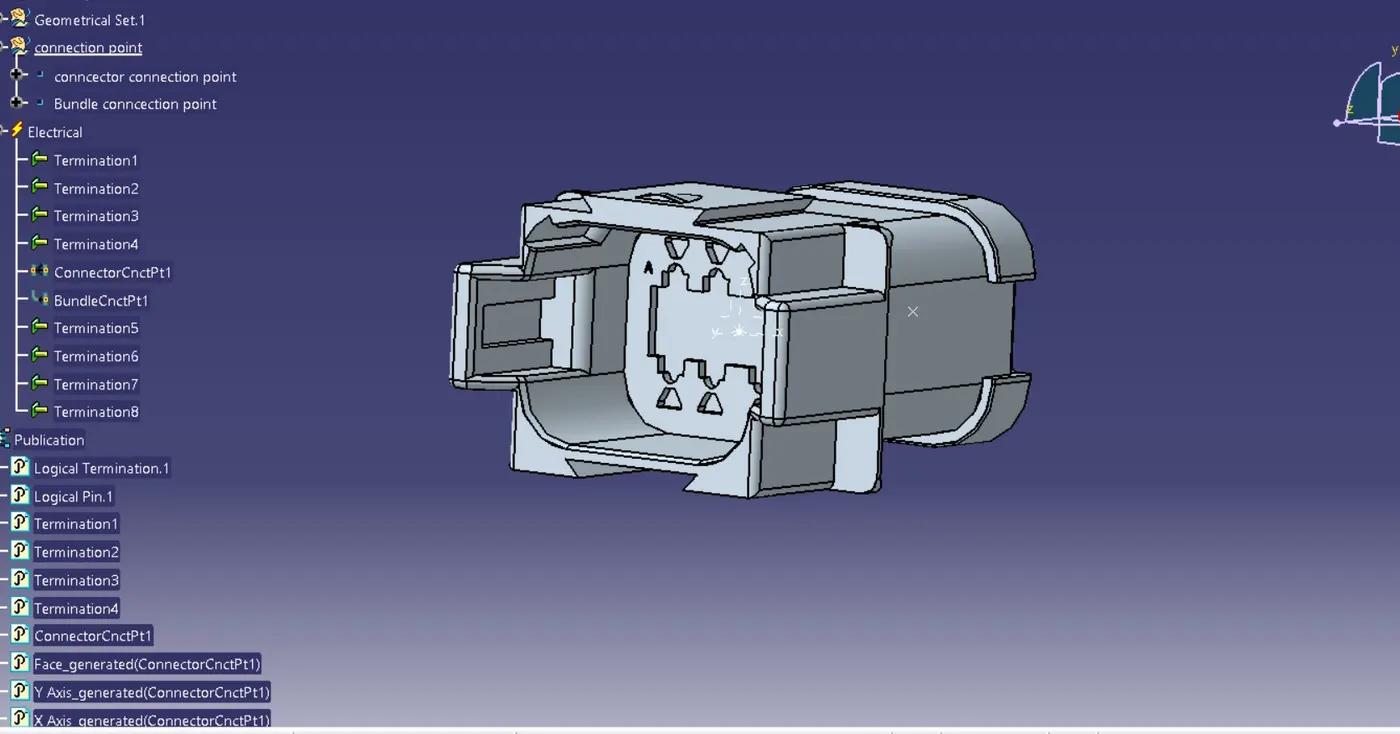
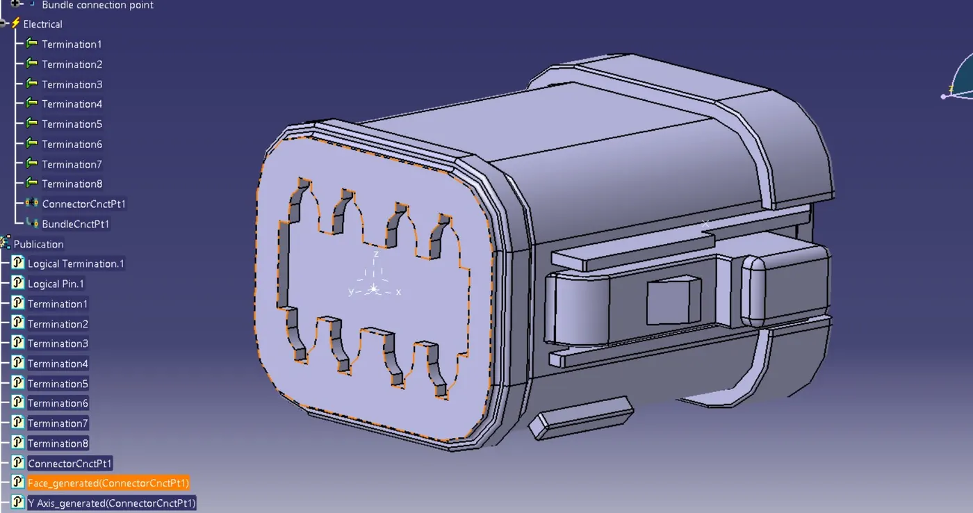
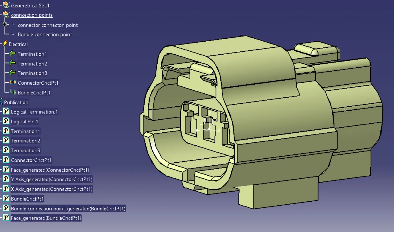
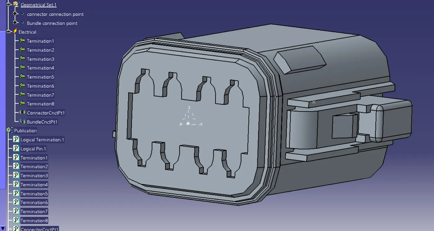
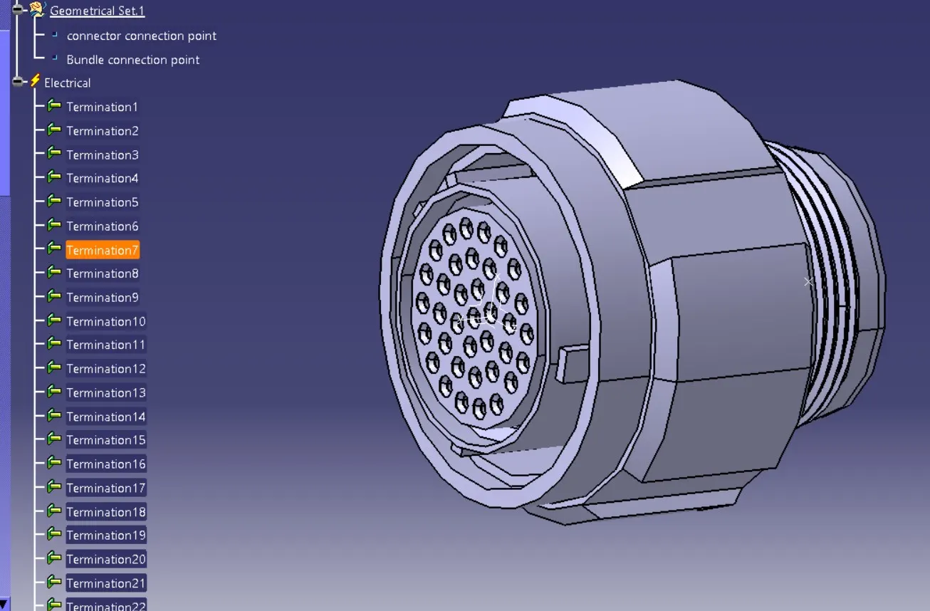
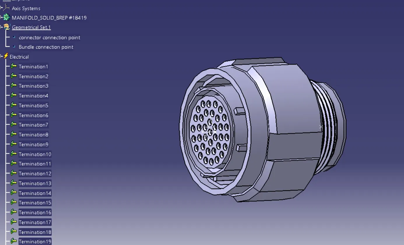
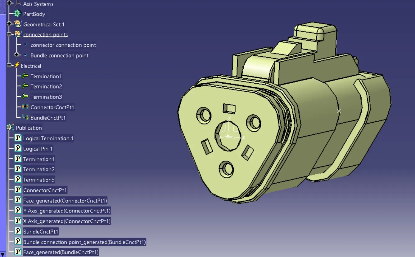
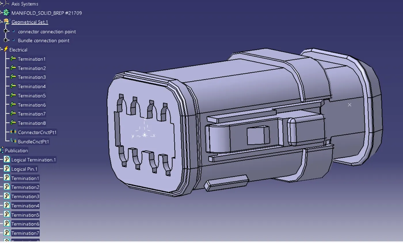
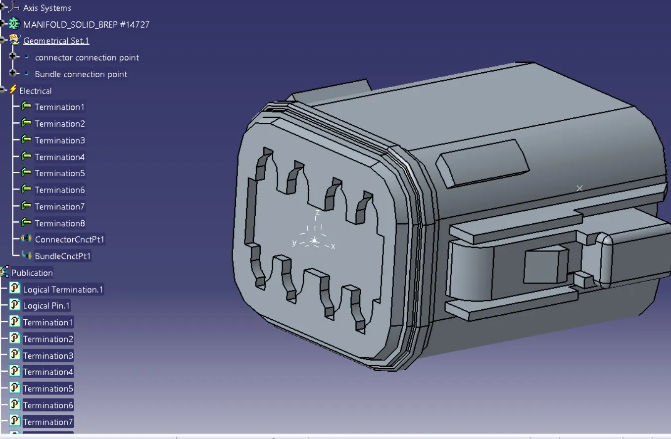
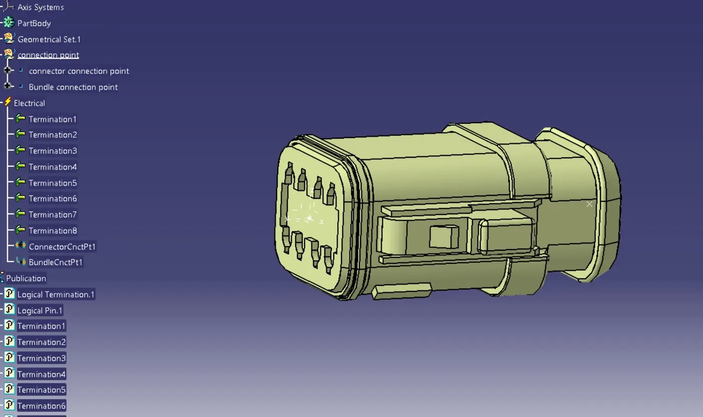
Then made catalogue for them separately for harness A and harness B
Ø Then go to catia and prepare a product file named it as Harness Context Assembly this is a top level product file that contains the harness electrical bundle.
Ø Then create sub product file to it called it as Geometrical Bundle A this is a wire harness product that contain all of the harness components that is clips ,support ,connectors etc.
Ø Create another sub product file and then open it in new window renamed it
Ø Geometrical Bundle B it contain all connectors and clips and annotations.
Ø Arrange all connectors to there required positions then go to electrical equipment and system -electrical harness discipline -electrical harness assembly .select geometrical bundle and then sub product file to define it electrically .
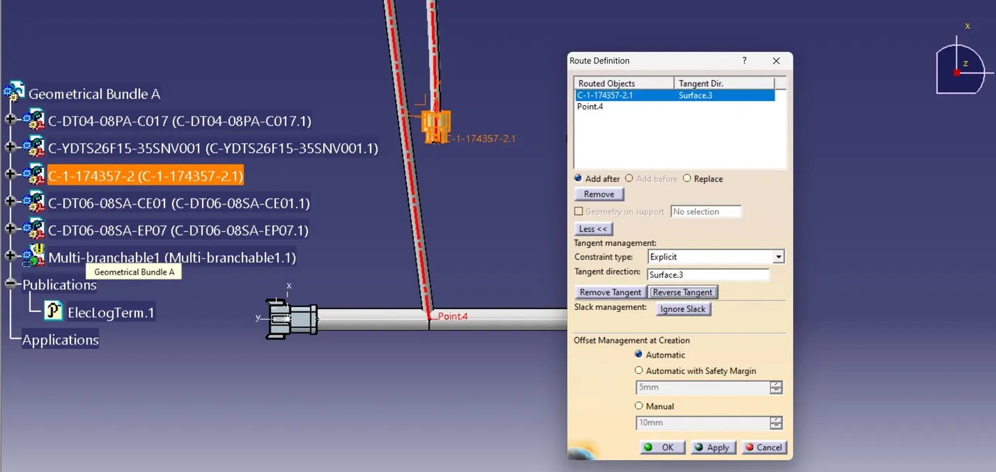
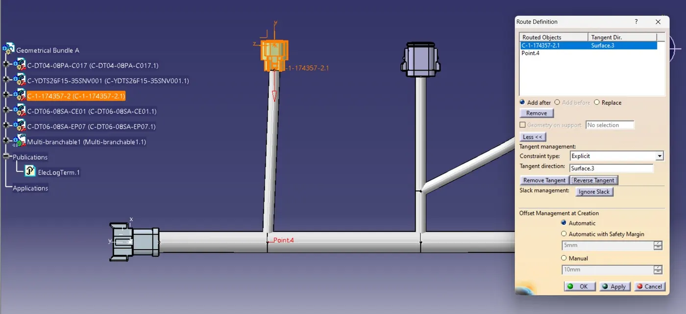
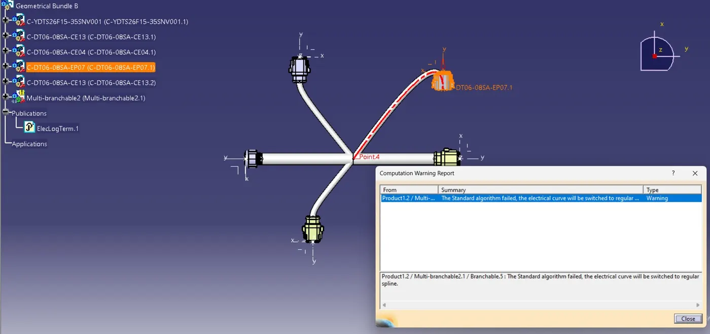
Ø Then go to multi branch able and select connectors to be join will open branch definition then define branch diameter and radius ratio as 20 and 1.5 then slack as zero then define tangent revers the tangent if required if tangent is not proper direction then will show geometrical warning and yellow icon in tree structure also gives this icon when proper slack was not gave.
Ø Define branch point in ratio if half add there 0.5 then connect another connector to this form branch definition command.
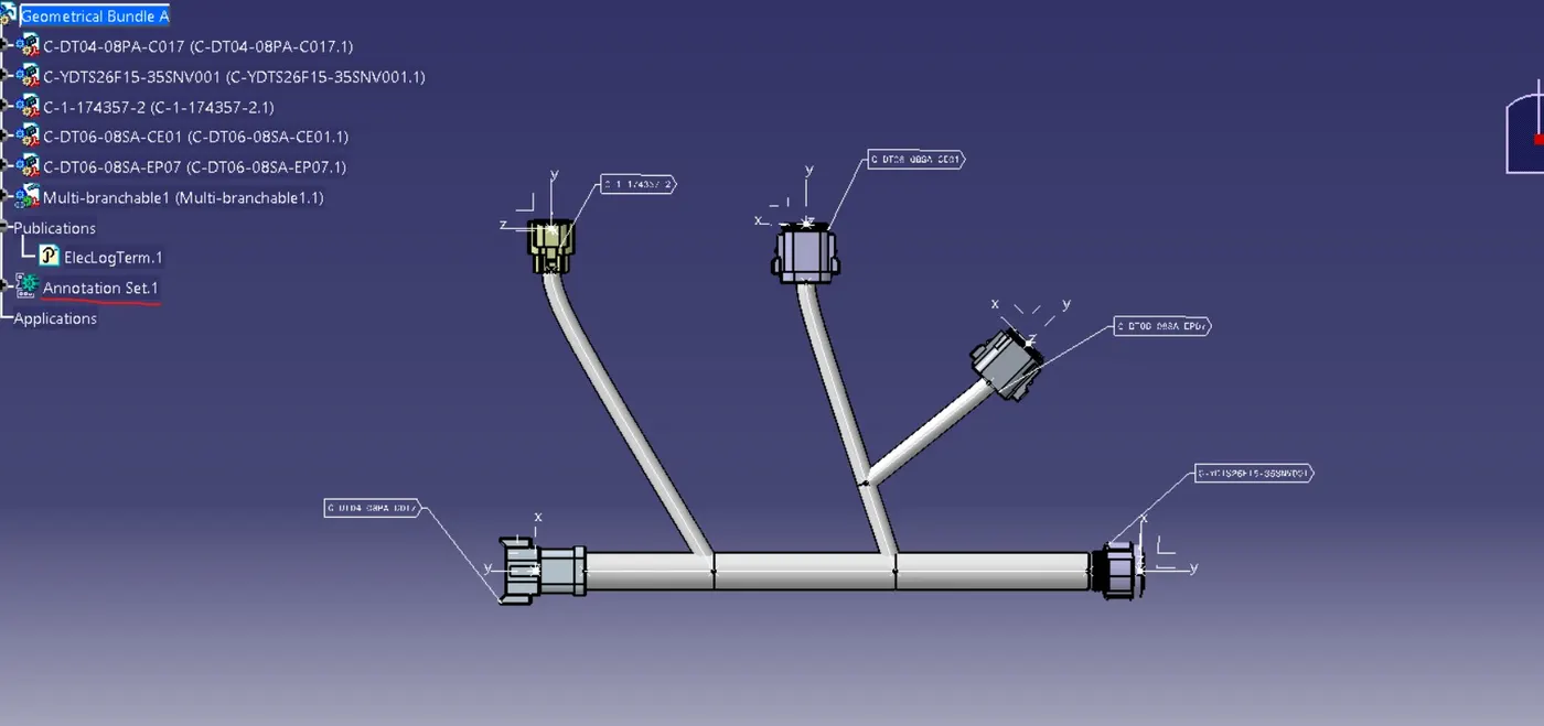
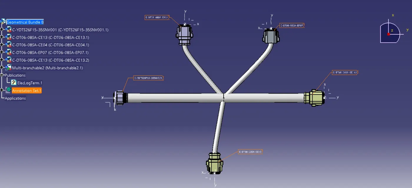
Ø After giving proper harness define annotation from mechanical assembly insert annotation or there is a command box side bar.
Ø Select plane to which want to add annotations and annotation plane or views and than click on flag notes select point and add flag there.
Ø Give name or number or types of connectors used there.
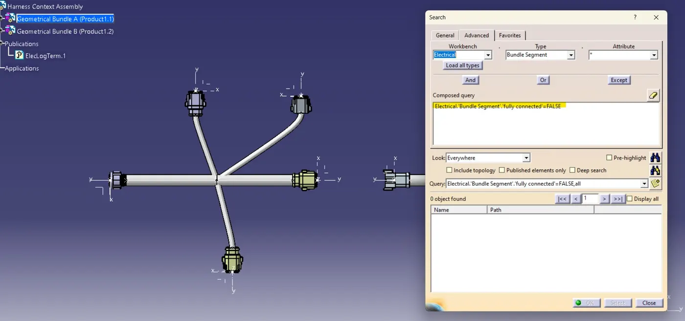
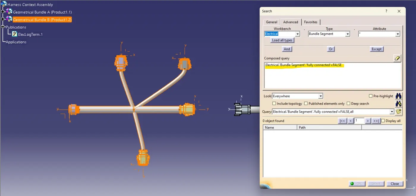
Ø Equipment and electrical harness discipline and then electrical assemble design and electrical connection point definition and connect electrical device options to connect them and disconnect them.
Ø Conversion of cat product file to cat part file:
I. Go to mechanical assembly workbench
II. Go to tools
III. Generate cat part from product
IV. Save this file or save as different them or same name
V. During this select igs or step option from bottom to select .
geomatrical bundle warning
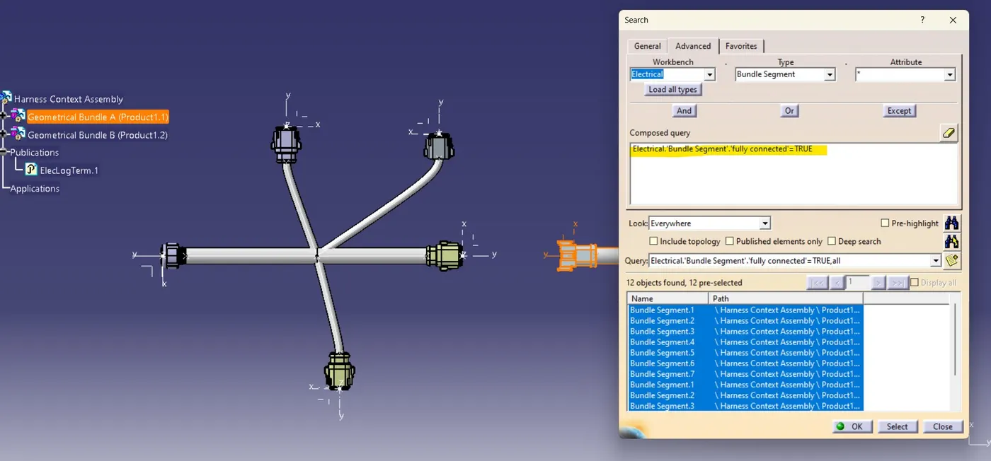
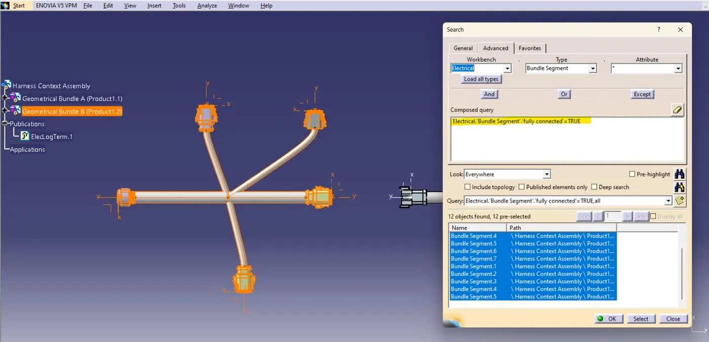
Checking connectivity:
Annotation :
Connectivity of two connectors:-