Wiring harness design in CATIA V5 - 3D modeling Week 5 & 6 Challenge
Wiring Harness Assembly Model
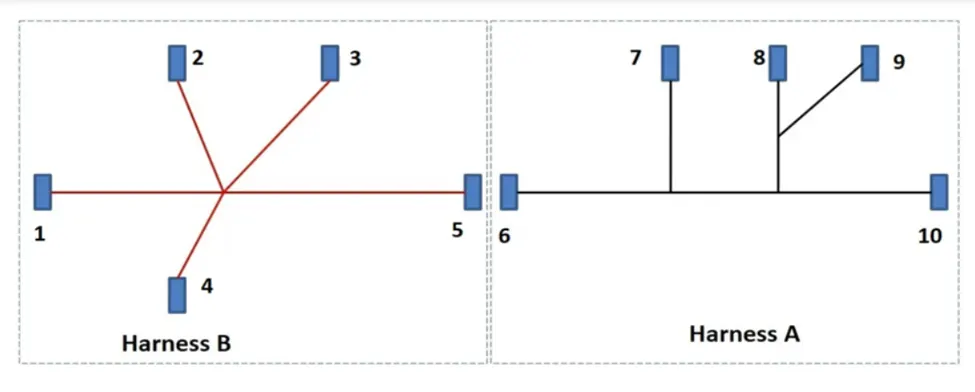
The goal here is make a model of wiring harness with reference to the given circuit diagram and connector cad data.
There are 10 connectors in the given circuit, so the first step in here is to define the connectors electrically. Both the connection point and bundle point are defined along with its electrical terminals. For ease of access of these connectors and to make a model of the harness in CATIA, these connectors are stored in a Catalog file. Let’s the name of the ‘catalog’ file be “AB-Catalog.” The connectors are renamed with prefix of alphanumeric characters for easy identification with respect to the input data.
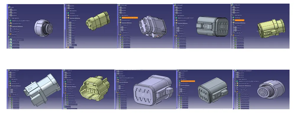
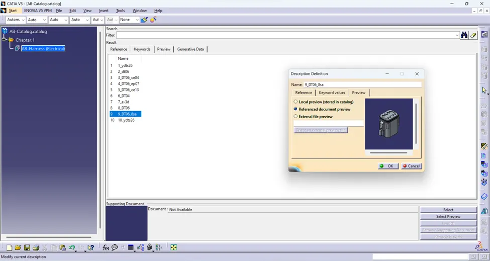
The above picture are snaps of the ten connectors which are defined electrically for wiring harness design. These are stored in the catalog file as shown below, the prefix numbers can be seen in the name column of the catalog file:
Since there are two circuits, we need to build two harness products. Working initially on “Harness_A”, the components are imported into the products (i.e., from 1 to 5) and aligned using assembly tools. Then under Electrical Harness Workbench, wiring harness is made first by initializing the file as geometric bundle, then navigating to multi-branchable to create the first wiring bundle. It’s usually connected between the extreme end connectors of the circuit. Then by adding the branch points, more branchable are created for completing the circuit. Sometimes the bundle tool gives out warnings in the formation of segments, such as “bundle is collapsed” which are generally due to tangency issue and bend radius mismatch. These can easily be rectified by adjusting the location of the connectors and increasing the bend radius. Tangency issue is mostly solved using reversal tab.
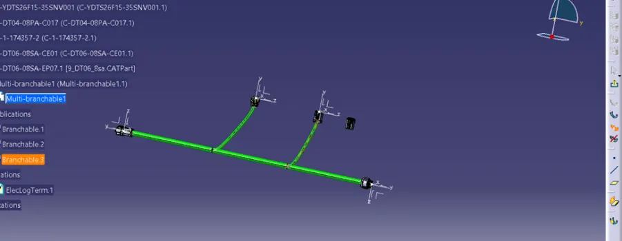
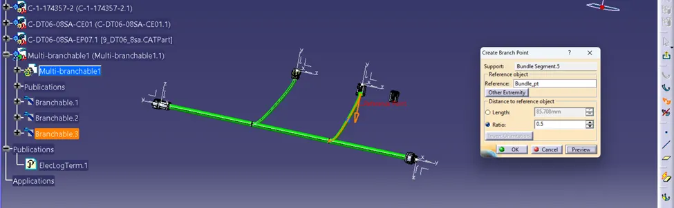
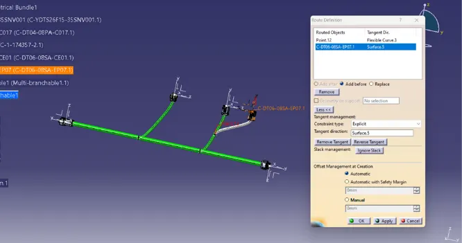
The above snap shows in-between steps of the bundle branch point and bundle segment creation. Sometimes errors too get popped in due to few reasons, such as the below picture;
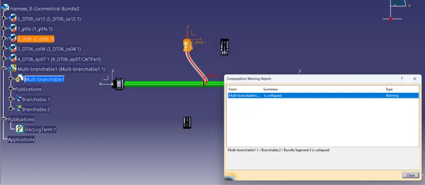
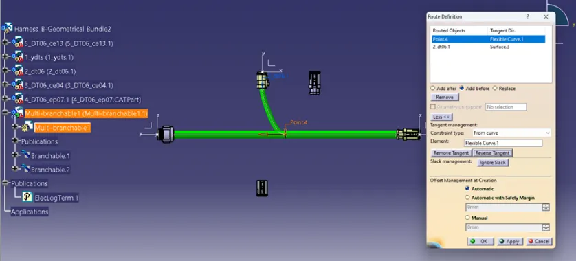
Such an error can be avoided by reverse tangent option, or modifying the position of the connector.
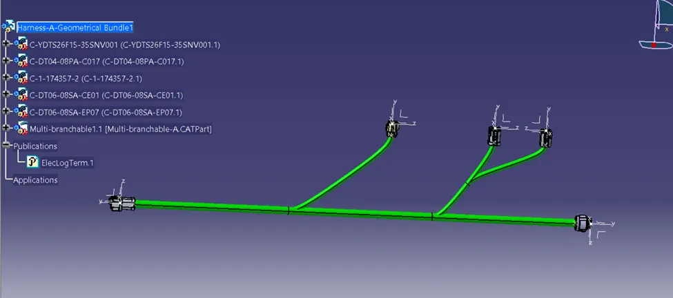
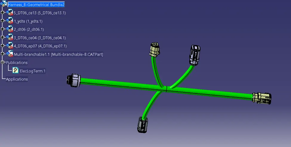
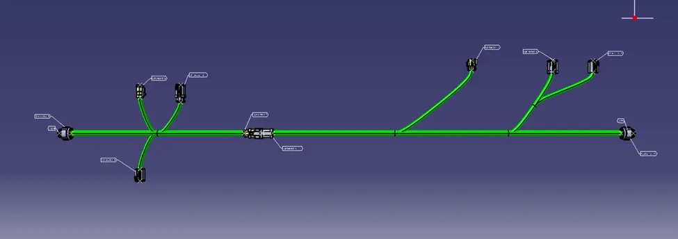
The above picture shows the wiring harness of "Circuit A" and the adjacent one of "Circuit B."
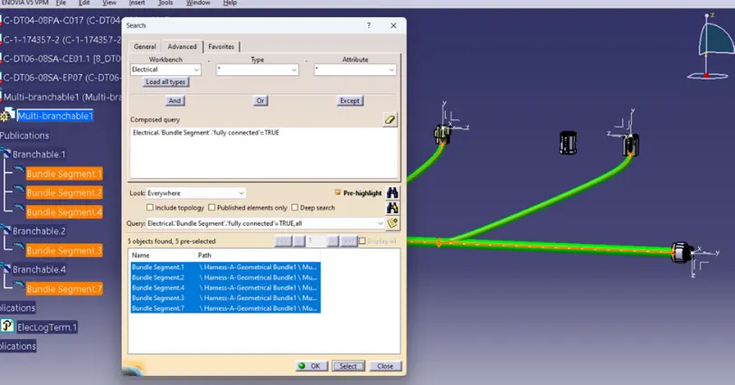
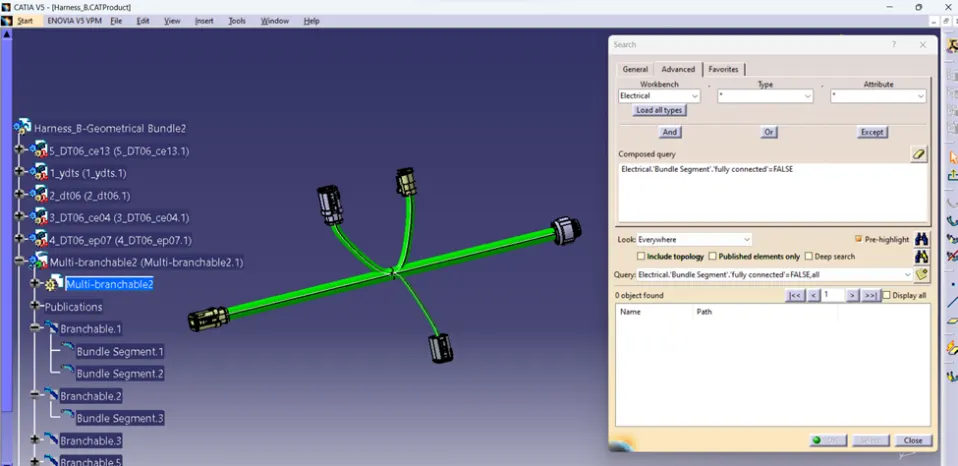
After the proper creation of the bundle segments, we need to check the continuity of the bundle. For a successful model of wiring harness all the bundle segments under “Multi-branchable” should have continuity. This can be checked using the search/find tool under Edit tab. The argument for the search parameter can be given as “Electrical.'Bundle Segment'.'fully connected'=FALSE” where the result gives us the bundle segments which are not connected to each other, where else the argument “Electrical.'Bundle Segment'.'fully connected'=TRUE” gives us the bundle segments which are connected to each other. The search argument can be selected graphically under the Advanced tab attributes of the Search Dialog box which pops up when we click Search (Ctrl+F) under Edit tab.
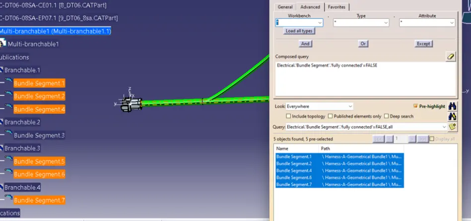
The above picture showcases the bundle segment discontinuity in the wiring Harness_A, using the Search tool. Under “Workbench” we need to select “Electrical”, under “Type” the selection should be “Bundle Segment”, and under “Attribute” the criteria should be “fully connected.” The condition of True and false can be as per the user needs.
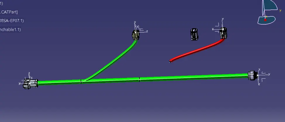
If there are any bundle discontinuity, the harness product is opened and multi-branchable workspace is activated to edit the bundle segments, if modifying the existing the bundle segment does not give the satisfactory condition we move to “Delete Special” command and delete the bundle segments and add the bundle segments as new branchable ensuring proper continuity.
The following picture shows the deletion of bundle segments which are not continuous and recreating from the multi-branchable.
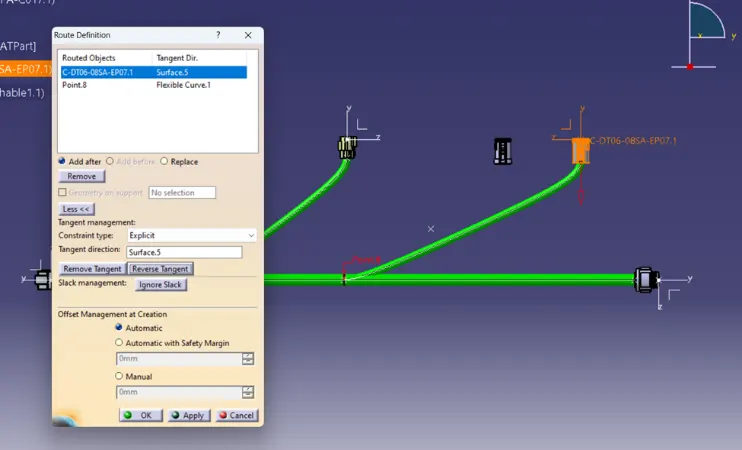
After the bundle segment is created, the bundle discontinuity is checked again before modifying other segments as shown in the picture below;
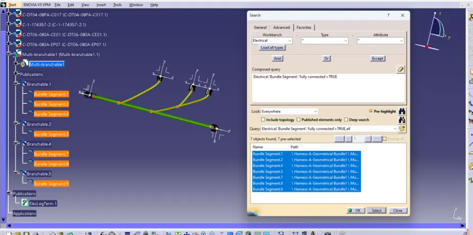
Similar steps are repeated until the bundles of both the products are continuous. The below snaps include the snaps of the harness products A and B where the Search tool shows all the bundle segments are fully connected;
After the both harness products are checked for discontinuity, they are imported into a new product for interconnection. For the interconnection of Harness_A and Harness_B, we have to change the workbench to Electrical Assembly Design. Under this workbench, “connector 5” and “connector 6” are connected using the tool named “Connect Electrical Devices” after which automatic constraints are made in the CATIA product.
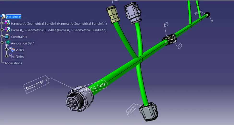
After the connection the circuit model is complete. Now we can add annotations to better emphasize the wiring model and give information to the CAD user. In order to annotate the harness model, we have to first change to Mechanical Assembly Workbench. The annotation notes are placed in an annotating plane, so as needed the planes are created with respect to connector surfaces. The Flag notes or texts are added to annotate the connectors and mating side properly.
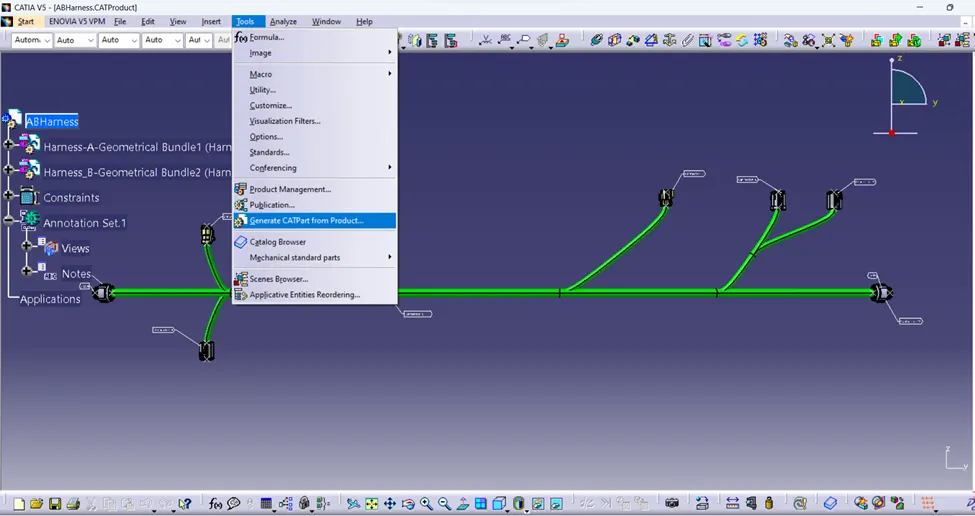
After the successful creation of the Wiring Harness Assembly Product, the file is needed to convert into CATIA part files for better use of cad data. For this purpose, under “Tool” tab section, select “Generate CATPart from Product..”, as shown below;
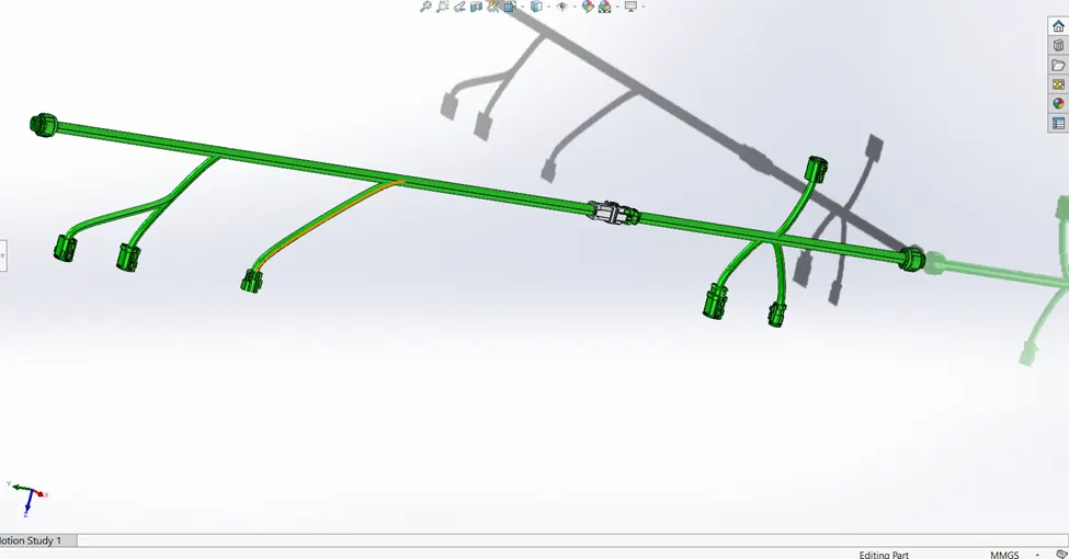
And finally for inter-operability for cad files, the final part is then converted to IGES format ("Save As" option is used). It will enable the cad data to be viewed and edited under multiple modeling software like PTC CREO, SEIMENS NX etc so that OEM and Supplier may work on it even if they have different CAD Software. Below is the snap of the same file opened in SOLIDWORKS;