Wiring harness design in CATIA V5 - 3D modeling Week 5 & 6 Challenge
WEEK 5 & 6 CHALLENGE
AIM - Route the following harness layout in Electrical workbench. Make assumption for harness bundle diameters. Use the connectors provided. After completion of routing,
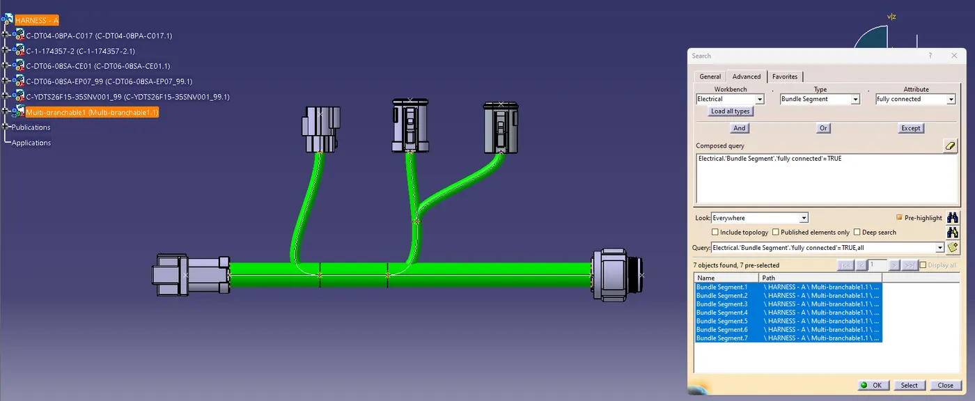
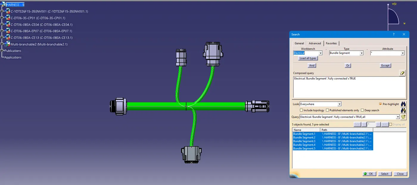
- Check the bundle Continuity. Add snap of result in submission
- Add annotation to all connectors. Make an assumptions for annotations like connect 1 , 2 etc
- Check for the bundle warning. Add snap.
- Generate CAT.part of harness assembly and convert is in. igs format.
INPUT
|
HARNESS B
|
HARNESS A
|
REPORT
- The given input is downloaded from the the given link.
- And is subjected to open in CATIA V5 part workbench to initiate the process of electrical defining with respect to bundle entry and connector connection points.
- The input is provided with two harness assemblies i.e., Harness A and Harness B with a total of 10 Connectors mentioned above with 5 each.
- PROCEDURE: -
- CAD part is loaded in partworkbench
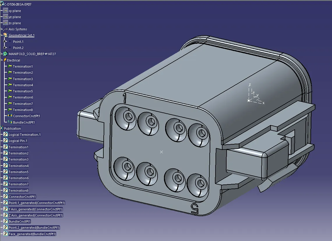
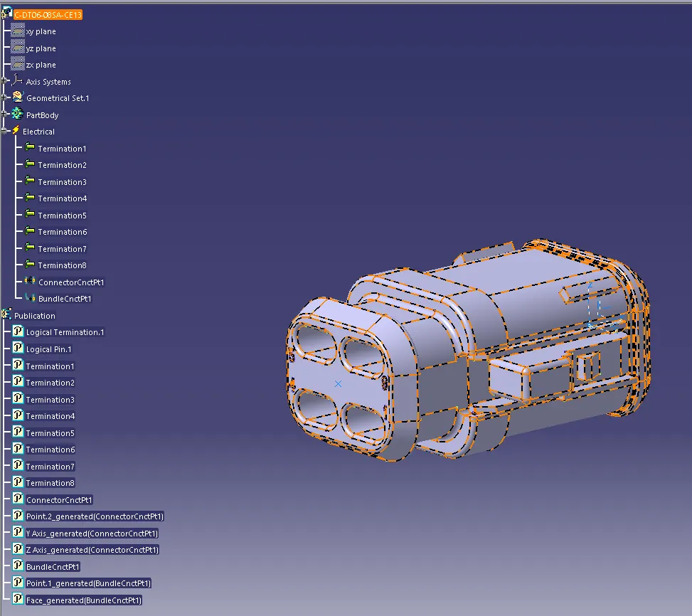
- Created Bundle entry and Connector Connection Point
- Switch to Electrical Part Workbench
- Defined Connector, Connector Connection Point, and Bundle Entry Point.
- Arranged the connectors in assembly workbench as per the assumed dimensions .
- Switch to Electrical Harness Assembly Design workbench
- Defined the product file as Geometrical Bundle and Created Multi-Branches to the connectors as per the layout diagram for both A and B assemblies.
- Checked the assemblies with Bundle Continuity option and ensured that all bundle segments are properly connected.
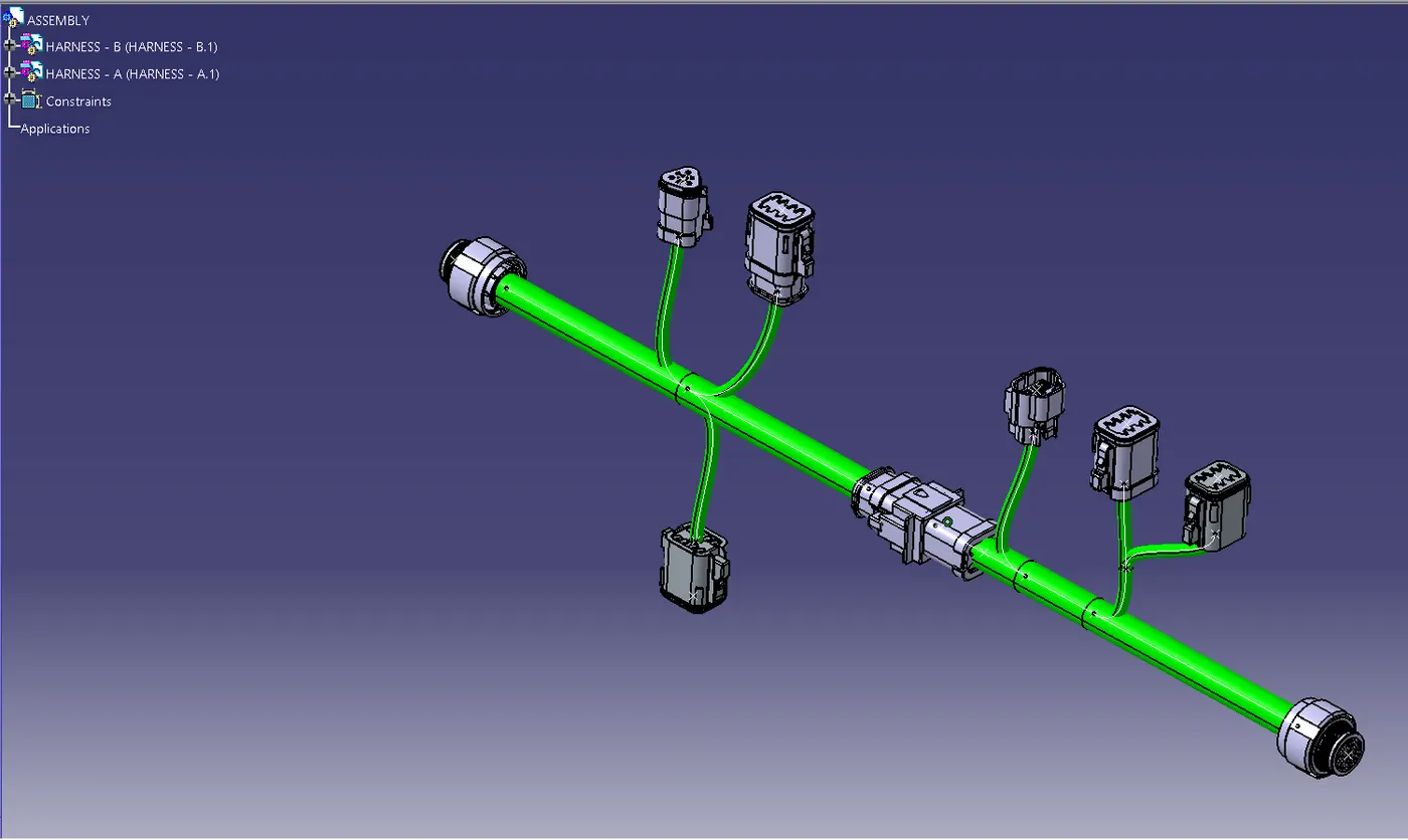
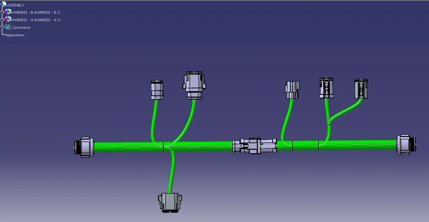
- Switch to Electrical Assembly design workbench and load both the Harness A and Harness B sub assemblies.
- Connect both assemblies using Connect electrical devices command in workbench.
- Annotate the assemblies to verify that the connectors are properly assembled.
- The CATPart has generated from the CATProduct file and is converted to .igs format as instructed to do.
- Catalogue has created and components are added on particular timing of creation.
- All the files, images, Catalogue, inputs used are provided in the below browse option, with each in separate folders.
IMAGES
- HARNESS A
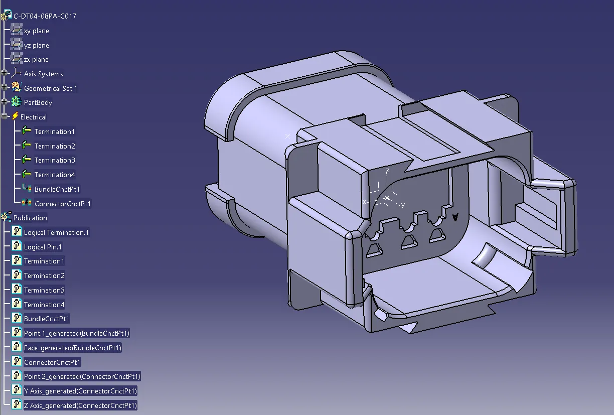
- 6 = DT04-08PA-C017
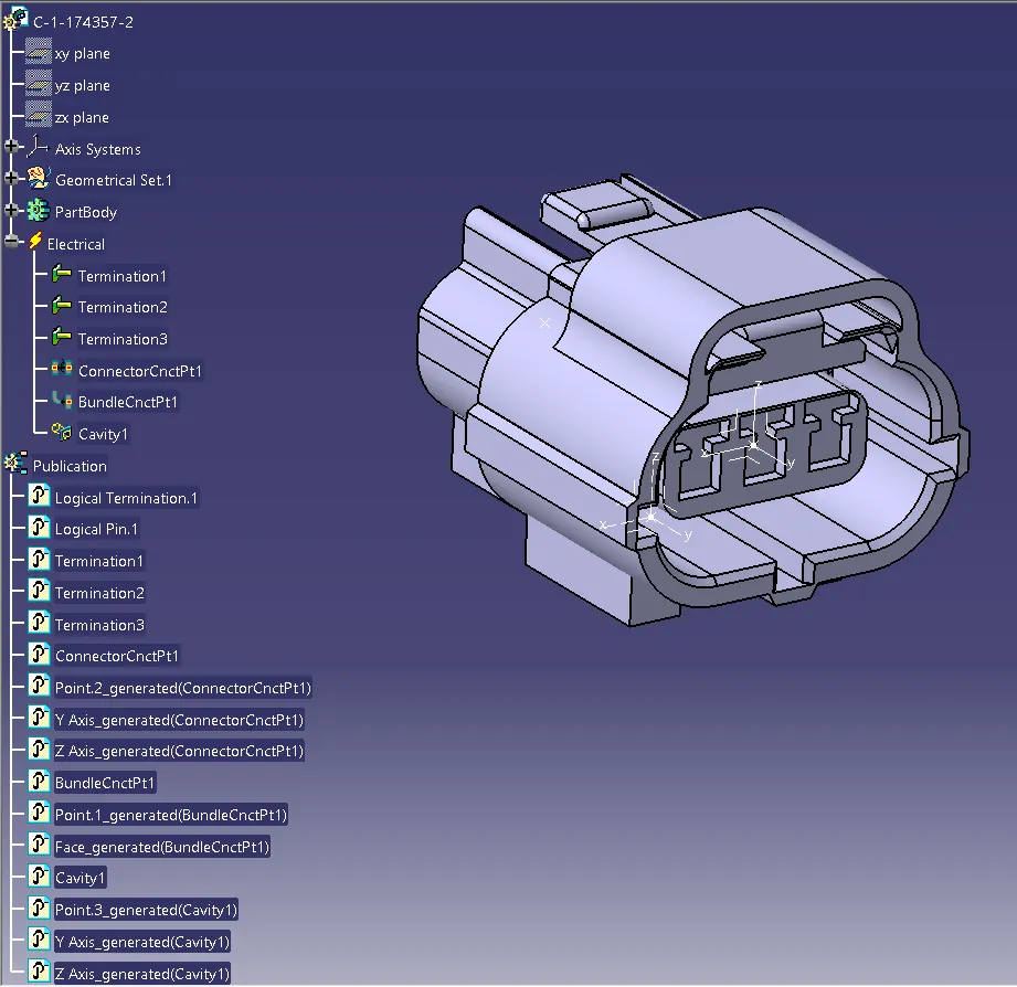
- 7 = 174357 - 2
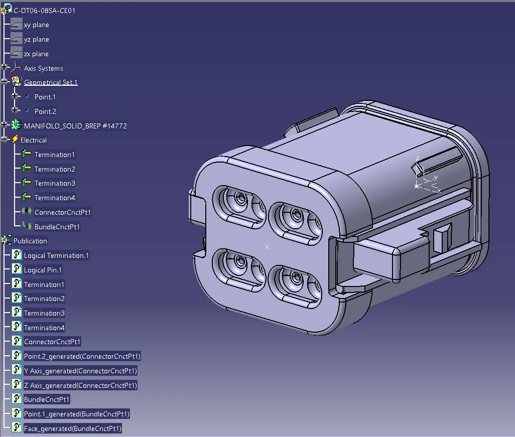
- 8 = DT06-08SA-CE01
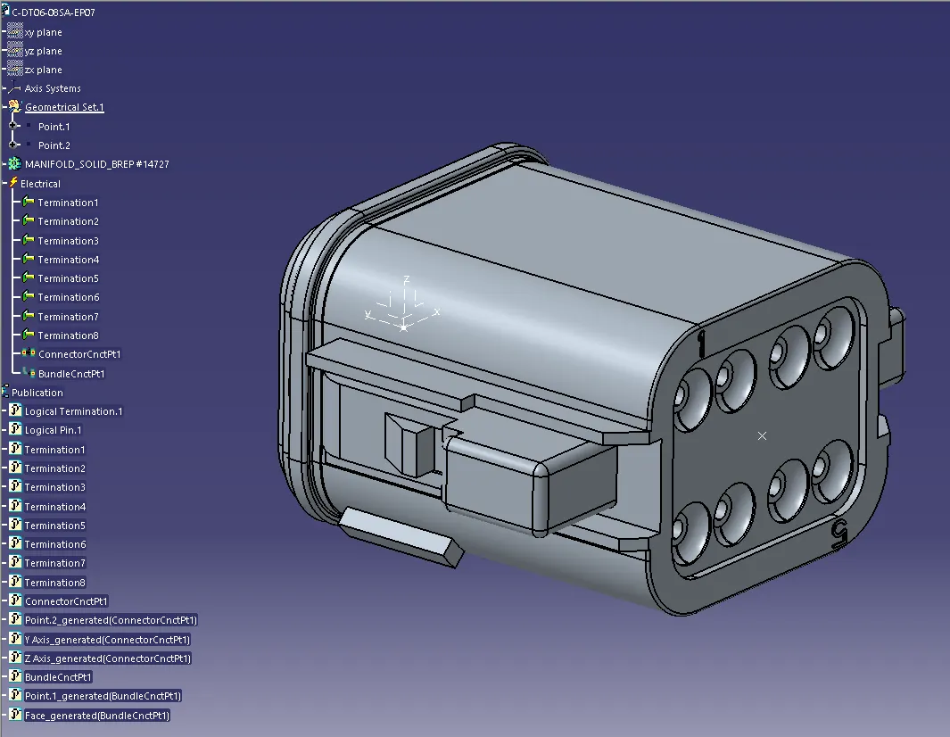
- 9 = DT06-08SA-EP07
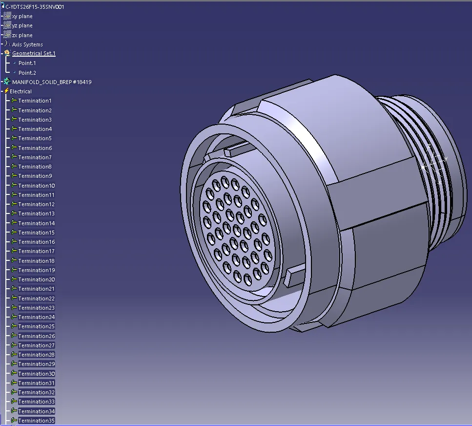
- 10 = C-YDTS26F15-35SNV001
- HARNESS B
- 1 = C-YDTS26F15-35SNV001
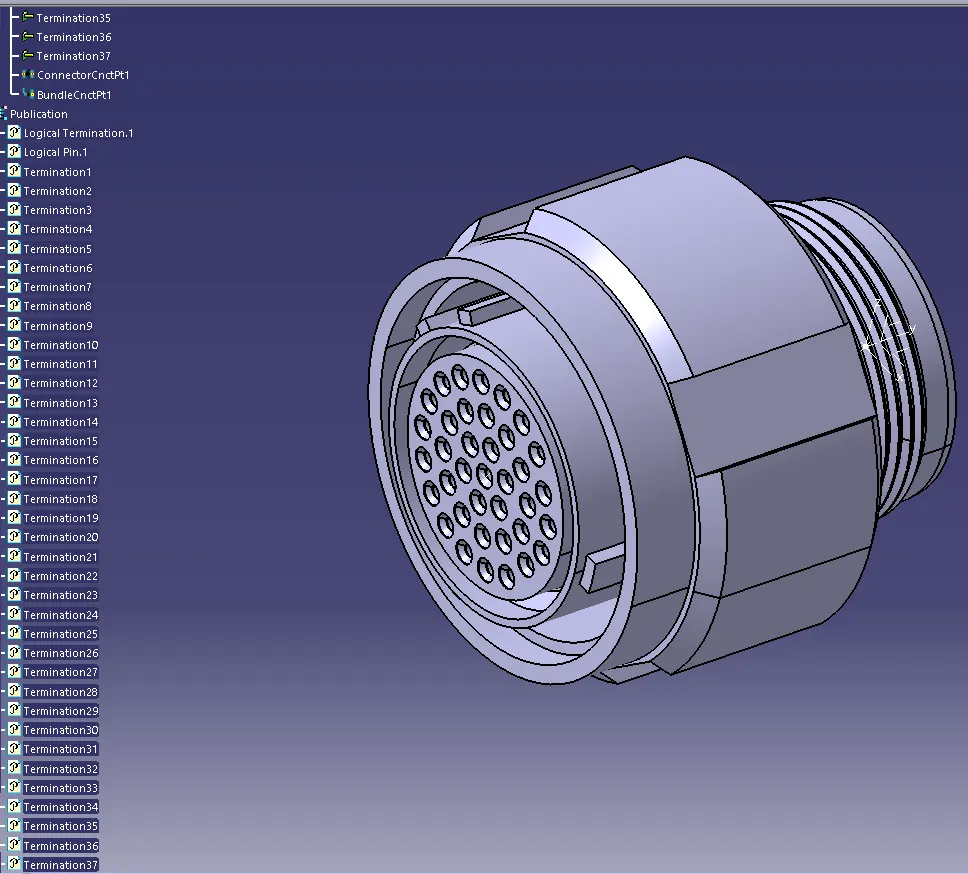
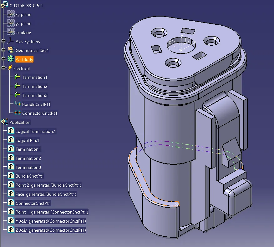
- 2 = DT06-3S-CP01
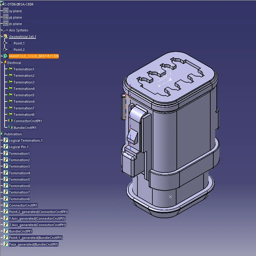
- 3 = DT06-08SA-CE04
- 4 = DT06-08SA-EP07
- 5 = DT06-08SA-CE13
- BUNDLE CONTINUITY
| HARNESS - A | HARNESS - B |
 |
 |
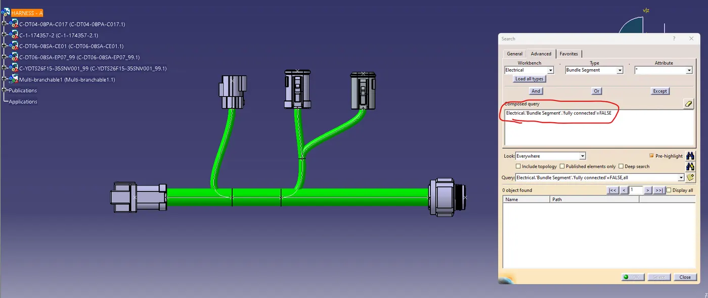 |
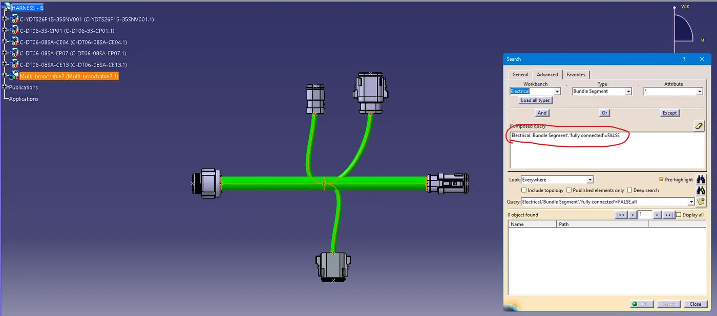 |
- ANNOTATIONS
| HARNESS - A | HARNESS - B |
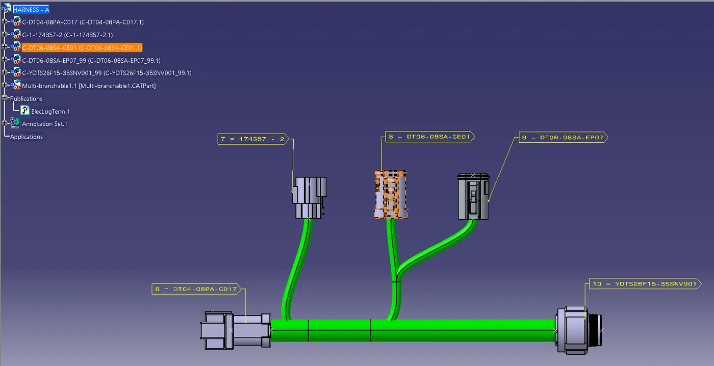 |
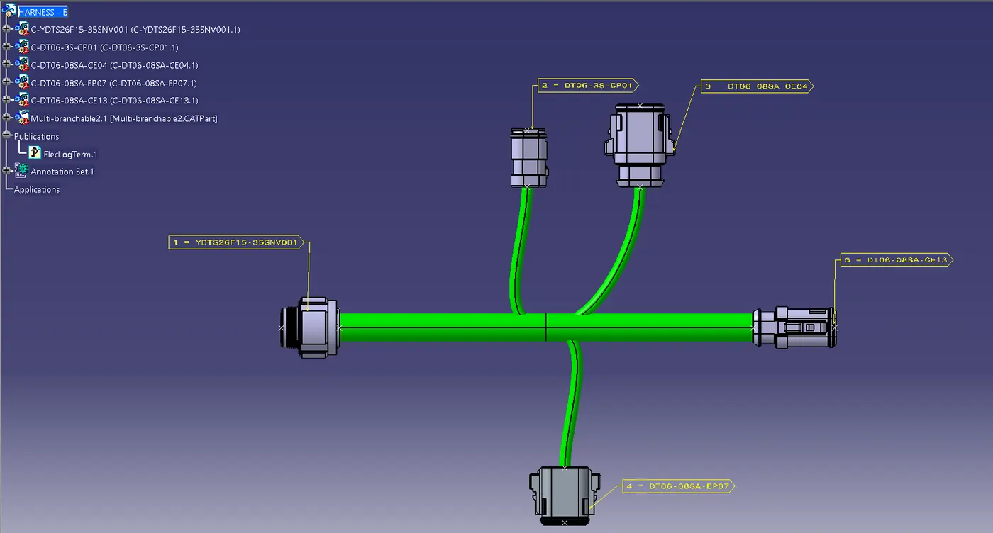 |
- ASSEMBLY
 |
 |
CONCLUSION
- Routed the harness layout in Electrical workbench
- Made assumption for harness bundle diameters.
- Checked the bundle Continuity
- Added annotation to all connectors
- Generated CAT.part of harness assembly and convert is in. igs format.
- Defined mechanical components electrically and prepared the catalogue for the same
- Prepared the interconnection for harness A and B.