Wiring harness design in CATIA V5 - 3D modeling Week 5 & 6 Challenge
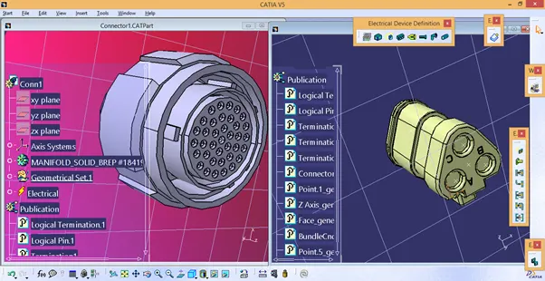
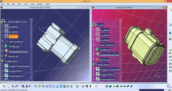
1) Define given cad file as Connectors in Electrical Part design workbench.
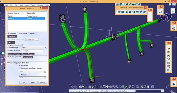
2) Create Harness Routing as per given specification.
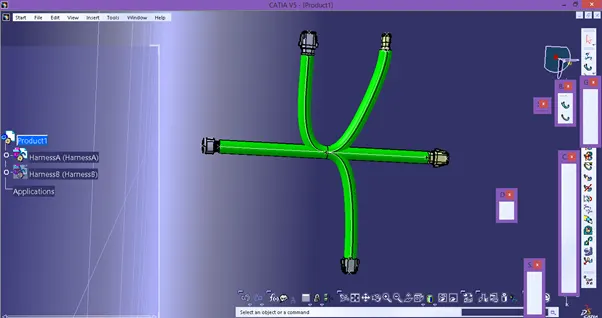
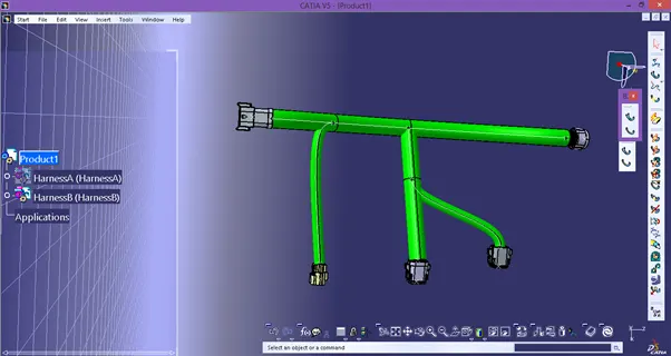
3) Check for Bundle segment connectivity.
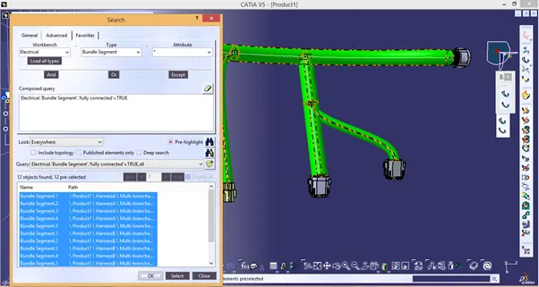
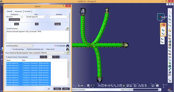
4) Electrical connectivity between two bundles can be established by using connect devices option in Electrical Assembly workbench.
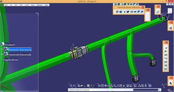
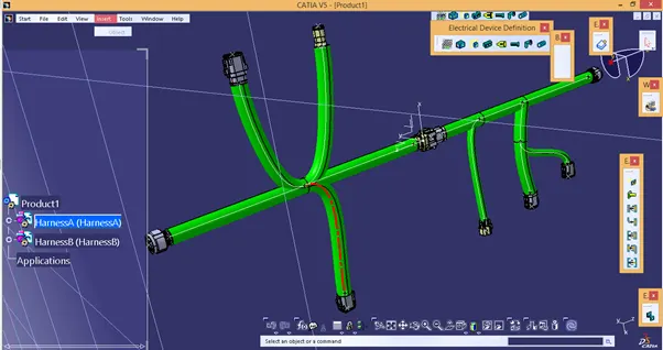
5) While establishing connectivity, the overall length of the Bundle segment varies and some bundle segment may show warnings as shown above. This can be solved by altering the slack length or bundle diameter as shown below:
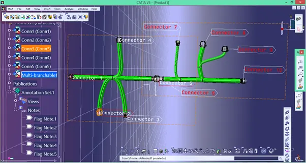
Switch to Assemblydesign workbench, add anotations to each connector.
6) Generate IGES file from the Assembly using Get a Cat Product option.
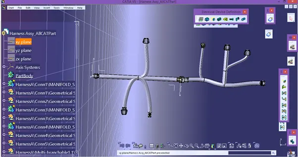
7) Save the Assembly as igs file.